Hardware PWM Signal Output
Overview
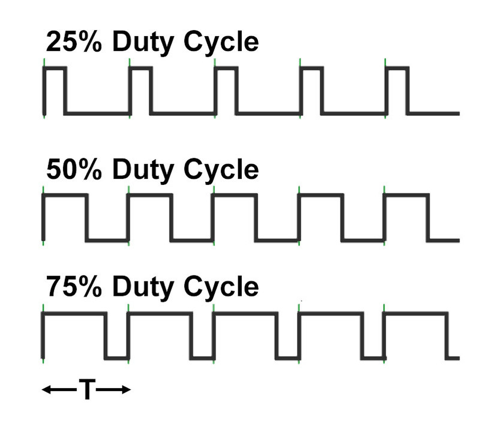
Generates PWM (Pulse Width Modulation) output with configurable frequency (Hz) and duty cycle (%). Can be used for various purposes including LED brightness control, servo motors, DC motor control, etc. Outputs hardware PWM signals using dedicated PWM pins.
Supported GPIO
- Raspberry Pi 0~4
- Raspberry Pi 5
- BeagleBone Black/Green
- Jetson Nano
Maximum output frequency for each hardware platform:
– Raspberry Pi 0~4: 30 MHz
– Raspberry Pi 5: 25 MHz
– BeagleBone Black/Green: 400 MHz
– Jetson Nano: 25 MHz
– Raspberry Pi 0~4: 30 MHz
– Raspberry Pi 5: 25 MHz
– BeagleBone Black/Green: 400 MHz
– Jetson Nano: 25 MHz
Commands
[INIT]
Configures initial PWM settings.
| Item | Type | Description |
|---|---|---|
| PWM Pin | WRITE | Selects the pin to output PWM signals. |
| Frequency (Hz) | WRITE | Sets the output frequency. |
[SET_DUTY_CYCLE]
Outputs PWM signal with the specified duty cycle.
| Item | Type | Description |
|---|---|---|
| Duty Cycle (%) | WRITE | Outputs PWM signal with the specified duty cycle (0~100%). |
Example
Objective
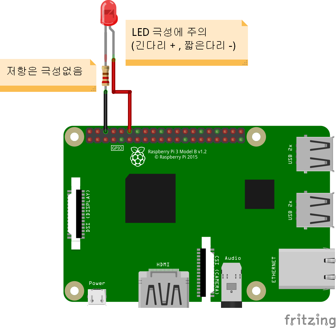
Control the brightness of a red LED by adjusting the PWM signal duty cycle from 0-100% using a dashboard slider widget.
Parts
| Part | Quantity |
|---|---|
| Raspberry Pi 4 * | 1 |
| Red LED | 1 |
| 220Ω Resistor ** | 1 |
* Other compatible hardware may be used. See Supported GPIO for details.
** For resistor value selection method, refer to here.
** For resistor value selection method, refer to here.
Wiring
Connect each component to the corresponding connection as listed in each row below.
| Component 1 | Component 2 | GPIO |
|---|---|---|
| LED + Pin | | 18 |
| LED – Pin | 220Ω Resistor | GND |