
Stepper Motor Control
Overview
Also known as step motor, this type of motor rotates by a fixed angle for each input pulse, making it suitable for precise position control or angle control. Multiple motors can be operated simultaneously, and each motor can be configured with continuous rotation or standby operations. Smooth motion can be achieved using acceleration and deceleration.
Supported GPIO
- Raspberry Pi 0~4
Stepper motors are driven through drivers. The driver types and representative models are described below:
| Type | Description | Models |
|---|---|---|
| 1 Pulse |
• STEP(PUL): Pulse input |
A4988, DRV8825, TB6600, A3967, etc. |
| 2 Pulse |
• CW: Clockwise pulse input |
DCM8027, DCM8054, MD2/5 series, etc. |
| 4 Pulse |
• IN1: Pulse 1 input |
L298N, L293D, ULN2003, etc. |
Commands
[INIT]
Configures initial settings for the stepper motor.
| Item | Type | Description |
|---|---|---|
| Driver Type | WRITE | Select the stepper motor driver type (1 pulse, 2 pulse, 4 pulse). |
| Steps per Revolution | WRITE | Enter the number of steps required for one complete revolution of the stepper motor. |
Driver Type: 1 pulse (STEP/DIR) Selected
| Item | Type | Description |
|---|---|---|
| STEP/PUL Pin | WRITE | Enter the GPIO pin to connect to the driver’s STEP/PUL. |
| DIR Pin | WRITE | Enter the GPIO pin to connect to the driver’s DIR. |
Driver Type: 2 pulse (CW/CCW) Selected
| Item | Type | Description |
|---|---|---|
| CW Pin | WRITE | Enter the GPIO pin to connect to the driver’s CW. |
| CCW Pin | WRITE | Enter the GPIO pin to connect to the driver’s CCW. |
Driver Type: 4 pulse (IN1~IN4) Selected
| Item | Type | Description |
|---|---|---|
| IN1 Pin | WRITE | Enter the GPIO pin to connect to the driver’s IN1. |
| IN2 Pin | WRITE | Enter the GPIO pin to connect to the driver’s IN2. |
| IN3 Pin | WRITE | Enter the GPIO pin to connect to the driver’s IN3. |
| IN4 Pin | WRITE | Enter the GPIO pin to connect to the driver’s IN4. |
| Excitation Mode * | WRITE | Select the excitation mode (Full step, Half step). |
| Item | Type | Description |
|---|---|---|
| Pulse Generation Time(ms) * | WRITE | Set the time interval for generating output pulses (Advanced). |
| Sync Control Group | WRITE | Set the group number this motor belongs to when using synchronized control. |
If the Raspberry Pi specifications are low or many tasks are running simultaneously, stepper motor rotation may become intermittent rather than continuous. Increasing the pulse generation time can resolve this issue.
However, response speed for motor start, stop, pause, and restart becomes slower as this value increases. For example, if pulse generation time is 1000ms (1 second), it may take up to 1 second for the stepper motor to actually stop after a stop command.
Therefore, for applications requiring fast response, set this value to the minimum 10ms, use a high-performance Raspberry Pi, and minimize concurrent tasks.
[ADD_MOTION]
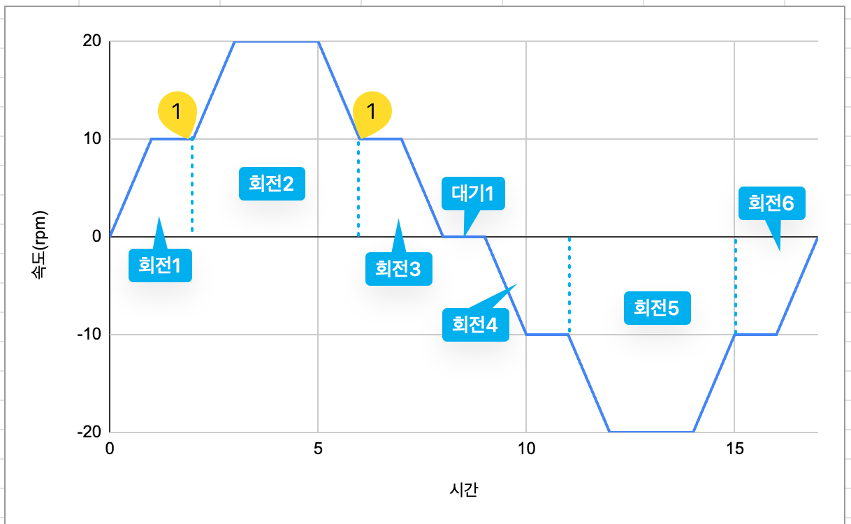
Adds a rotation motion to the stepper motor buffer. The motor rotates with the target speed and rotation amount (revolutions or pulses), and can start and stop smoothly using acceleration and deceleration. This command can be combined with ADD_DELAY to configure multiple rotation or standby operations to execute consecutively.
| Item | Type | Description |
|---|---|---|
| Speed (rpm) | WRITE | Enter the stepper motor’s revolutions per minute (rpm). |
| Rotation Unit | WRITE | Select rotation unit (Steps, Revolutions, Position, Continuous). |
| Steps 1 | WRITE | Enter the number of steps to rotate. Negative values rotate in opposite direction. |
| Revolutions 2 | WRITE | Enter the number of revolutions to rotate. Negative values rotate in opposite direction. |
| Position 3 | WRITE | Enter the target position to move to. |
| Direction 4 | WRITE | Select rotation direction (Forward, Reverse). |
| Acceleration (rpm/s) 5 | WRITE | Enter acceleration when starting rotation (speed increase per second). |
| Deceleration (rpm/s) 5 | WRITE | Enter deceleration when ending rotation (speed decrease per second). |
2 Displayed only when rotation unit is “Revolutions”.
3 Displayed only when rotation unit is “Position”.
4 Displayed only when rotation unit is “Continuous”.
5 For example, if starting from standstill with target rotation speed of 60 rpm and acceleration/deceleration of 60 rpm/s, the motor will smoothly accelerate from 0→60rpm over 1 second when starting and smoothly decelerate from 60→0rpm over 1 second when stopping.
[ADD_DELAY]
Adds a standby operation to the stepper motor buffer. The motor will remain stationary for the set time duration. This command can be combined with ADD_MOTION to configure multiple rotation or standby operations to execute consecutively.
| Item | Type | Description |
|---|---|---|
| Delay Time | WRITE | Enter the time for the stepper motor to wait in stationary state. |
[RUN]
Operates the stepper motor according to the rotation (ADD_MOTION) or standby (ADD_DELAY) operations stored in the buffer. Below is an operation example.
[STOP]
Stops the stepper motor.
[PAUSE]
Pauses the stepper motor.
[RESUME]
Resumes the stepper motor.
[CLEAR]
Clears and initializes the stepper motor buffer.
[RUN_SYNC]
Operates multiple stepper motors in synchronized motion mode. Use this when precise timing control of multiple stepper motors is required. If a motor completes its operation first, it must wait until all other motors complete their operations.
| Item | Type | Description |
|---|---|---|
| Group Number | WRITE | Enter the stepper motor group number to operate in synchronized mode. |
Below is an example of operating two stepper motors in synchronized control mode.
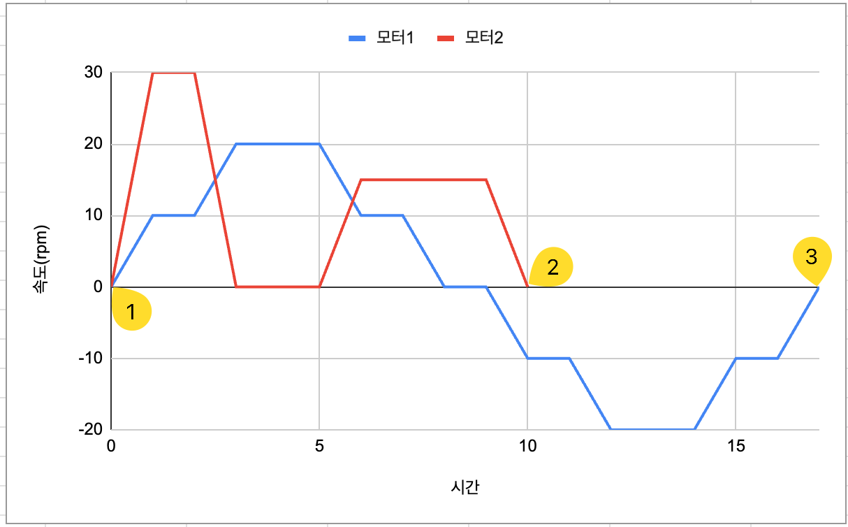
2. Motors that complete their operation first wait until all other motors finish.
3. Synchronized control is completed.
[STOP_ALL]
Stops all running stepper motors.
[PAUSE_ALL]
Pauses all running stepper motors.
[RESUME_ALL]
Resumes all paused stepper motors.
[CLEAR_ALL]
Clears and initializes buffers for all stepper motors.
[SET_POSITION]
Sets the stepper motor’s current position to the entered value.
| Item | Type | Description |
|---|---|---|
| Position | WRITE | Enter the value to set as current position (e.g., set to origin → 0). |
[GET_POSITION]
Reads the stepper motor’s current position.
| Item | Type | Description |
|---|---|---|
| Position | READ | Current position of the stepper motor. |
[GET_STATUS]
Reads the stepper motor’s current status.
| Item | Type | Description |
|---|---|---|
| Status | READ | Current status of the stepper motor (0: Stopped, 1: Paused, 2: Running). |
[EMG_STOP]
Immediately performs emergency stop for all running stepper motors.
Example
Objective
When clicking the dashboard button widget, operate the stepper motor according to the motion profile below. Must include acceleration and deceleration during rotation start and stop.
- 3 revolutions clockwise
- 1 second delay
- 3 revolutions counter-clockwise
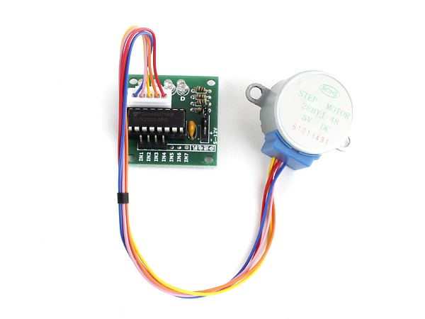
Parts
| Part | Quantity |
|---|---|
| Raspberry Pi 4 | 1 |
| 28BYJ-48 Stepper Motor | 1 |
| ULN2003 Driver | 1 |
| 5V DC Power Supply | 1 |
Wiring
Connect each component to the corresponding connection as listed in each row below.
| 5V DC Power ** | Driver | GPIO |
|---|---|---|
| | IN1 | 23 * |
| | IN2 | 24 * |
| | IN3 | 25 * |
| | IN4 | 8 * |
| + | + (5~12V) | |
| – | – | GND |
** Use an appropriate external DC power supply that matches the stepper motor’s type, voltage, and current consumption.

