
RGB LED Color Control
Overview
A library for controlling RGB LED colors using PWM signals.
Supported GPIO
- Raspberry Pi 0~4
- Raspberry Pi 5
- BeagleBone Black/Green
Commands
[INIT]
Enters initial configuration settings.
| Item | Type | Description |
|---|---|---|
| R Pin * | WRITE | Enter the GPIO pin number connected to the R pin or select a PWM pin. |
| G Pin * | WRITE | Enter the GPIO pin number connected to the G pin or select a PWM pin. |
| B Pin * | WRITE | Enter the GPIO pin number connected to the B pin or select a PWM pin. |
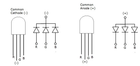
| Module Type ** | WRITE | Select the module type. (Anode, Cathode) |
* Raspberry Pi 0~4 can use any GPIO pins, while other hardware can only use PWM output pins.
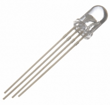
** If the RGB LED has a + pin, it’s an Anode type; if it has a – pin, it’s a Cathode type.
** If the RGB LED has a + pin, it’s an Anode type; if it has a – pin, it’s a Cathode type.
[SET_RGB]
Sets the RGB color of the LED.
| Item | Type | Description |
|---|---|---|
| R | WRITE | Enter the R value of the color. (0~255) |
| G | WRITE | Enter the G value of the color. (0~255) |
| B | WRITE | Enter the B value of the color. (0~255) |
Example
Objective
Change RGB colors using the R, G, B color slider widgets on the dashboard.
Parts
| Part | Quantity |
|---|---|
| Raspberry Pi 4 * | 1 |
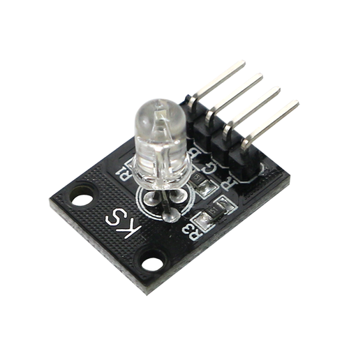
| RGB LED Module ** | 1 |
* Other hardware can also be used. Refer to Supported GPIO.
** The module includes necessary resistors.
** The module includes necessary resistors.
Wiring (Cathode Type)
Connect each component to the corresponding connection as listed in each row below.
| RGB LED Module | GPIO |
|---|---|
| R | 14 * |
| G | 15 * |
| B | 18 * |
| – | GND |
* Any GPIO pins can be used.
