Grablo Help Grablo Help
  • User Manual
  • Tips
  • News
  • Go to
    • Grablo Home
    • Grablo App
  • 한국어
Grablo Help Grablo Help
문의하기
Grablo Help Grablo Help
  • User Manual
  • Tips
  • News
  • Go to
    • Grablo Home
    • Grablo App
  • 한국어
loading
  1. Home
  2. User Manuals
  3. I/O Device
  4. DC Motor Control
Updated on August 11, 2025

User Manuals

  • Folder icon closed Folder open iconQuick Start Guide
    • Grablo!
    • Basic Concepts
  • Folder icon closed Folder open iconProject
    • General
    • Sharing Project
  • Folder icon closed Folder open iconLogic
    • Logic
    • Control Group
    • Control
    • Condition Group
    • Action Group
    • Condition
      • General
      • Type
        • Always Met
        • Once Met
        • Variable Comparison
        • Schedule
        • Time Range
        • Time Interval
        • Condition Reference
        • Action Reference
        • Change Detection
        • Custom Condition
    • Action
      • General
      • Type
        • Write Variable
        • I/O Device Control
        • Time Delay
        • Timer
        • Display Image
        • Play Media
        • Synthesizer
        • Audio Recording
        • Audio Transform
        • Shell Command
        • Speech-to-Text
        • Text-to-Speech
        • File System
        • Read/Write File
        • Database
        • HTTP Communication
        • MQTT Communication
        • OPC UA Communication
        • Modbus Communication
        • Send Email
        • Telegram Message
        • User Defined Communication
        • PID Control
        • Statistics
        • Collection
        • Custom Action
  • Folder icon closed Folder open iconDashboard
    • General
    • Widgets
  • Folder icon closed Folder open iconSetting
    • GPIO
    • Variables
    • I/O Device
    • File Editor
    • Collection
    • Timer
    • Image Viewer
    • Audio Transfrom
    • Media Player
    • Synthesizer
    • Text-to-Speech
    • Speech-to-Text
    • Audio Recorder
    • MQTT Client
    • OPC UA Client
    • Modbus
    • Email Client
    • Telegram Bot
    • Database
    • User Defined Communication
    • PID Control
    • Statistics
  • Folder icon closed Folder open iconI/O Device
    • DS18B20 Digital Temperature Sensor
    • MAX31865 RTD Temperature Sensor
    • TinyGPS++ GPS Library
    • BMP180 Digital Pressure and Temperature Sensor
    • AHTx0 Temperature and Humidity Sensor
    • SHT2x Temperature and Humidity Sensor
    • Servo Motor Control
    • PWM Signal Output
    • PWM Signal Monitoring
    • Hardware PWM Signal Output
    • LED Control
    • Push Button Input
    • Digital I/O
    • Stepper Motor Control
    • High Speed Counter
    • ADS1x15 ADC
    • ADXL345 3-Axis Accelerometer
    • BME280 Temperature, Humidity, Pressure Sensor
    • BMP280 Temperature, Pressure Sensor
    • MLX90614 Infrared Temperature Sensor
    • MCP4725 DAC
    • QMC5883L 3-Axis Magnetometer
    • SHT31 Digital Temperature and Humidity Sensor
    • TCS34725 RGB Color Sensor
    • VEML6070 UV Sensor
    • BH1750 Digital Light Intensity Sensor
    • DS3231 RTC High-Precision Real-Time Clock
    • MPU-9250 9-Axis IMU Sensor
    • CCS811 Carbon Dioxide and TVOC Air Quality Sensor
    • VL53L0X ToF Laser Distance Sensor
    • TFmini Plus(S) LiDAR Distance Sensor
    • MAX7219 8-Digit 7-Segment Display
    • PCF8574 LCD Display Driver
    • HC-SR04 Ultrasonic Distance Sensor
    • LED Brightness Control
    • RGB LED Color Control
    • DC Motor Control
    • AT24C256 EEPROM Memory
    • DHTxx Temperature and Humidity Sensor
    • MCP3xxx ADC
    • LCD Display Driver (MCP23008, MCP23017)
    • MFRC522 RFID Reader
    • Passive Buzzer
    • NeoPixel (WS281x) LED
    • Infrared (IR) Receiver
    • NeoPixel Matrix
    • ST77xx TFT Color LCD
    • ILI9341 TFT Color LCD
    • SSD1306 0.96-inch Monochrome OLED Display
    • SH1106 1.3-inch Monochrome OLED Display
    • MAX7219 8×8 LED Dot Matrix
    • HT16K33 4-Digit 7-Segment Display
    • HX711 Load Cell 24-bit AD Converter
    • TCS3200 RGB Color Sensor
    • MPU6050 6-Axis Gyro Accelerometer
    • TM1637 4-Digit 7-Segment Display
    • PM2008(M) Particulate Matter Sensor
    • PMS x003 Particulate Matter Sensor
    • MAX30102 SpO2 and Heart Rate Sensor
    • AS608, FPM10A Fingerprint Sensor
    • TTP229 Capacitive 16-Key Touch Keypad
    • 4×4 Keypad Matrix
    • Analog to Digital Converter (ADC)
    • Digital to Analog Converter (DAC)
    • RPM Monitor
    • PCA9685 16-Channel 12-Bit PWM Servo Driver
    • INA219 DC Current Sensor
    • VL6180X ToF Distance Sensor
    • Custom Digital Waveform Output
    • NRF24L01 2.4GHz RF Module
  • Folder icon closed Folder open iconBlock Coding
    • General
    • Blocks
      • Values
      • Logic
      • Loop
      • Math
      • Date/Time
      • Text
      • Byte Array
      • List
      • Type Conversion
      • Unit Conversion
      • Science
      • Bit/Byte
      • Complex Numbers/Vectors
      • JSON
      • XML
      • Local Variables
      • Local Functions
  • Folder icon closed Folder open iconConnect & Run
    • Hardware and Operating System
    • Grablo Package Installation
    • Connect and Run

DC Motor Control

Estimated reading: 3 minutes 292 views

Overview

A library for controlling DC motors using PWM signals. DC motors are driven through motor drivers, and various types of drivers exist.

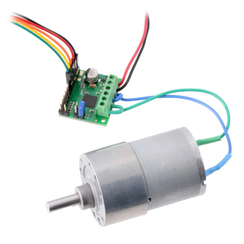
​The types and descriptions of DC motor drivers are as follows:

Type Description Models
Type 1

• ENA/B: Speed control
• IN1: Forward direction
• IN2: Reverse direction

L298N, L293D, TB6612FNG, etc.
Type 2 • IN1: Forward speed control
• IN2: Reverse speed control
L9110, DRV8833, etc.
Type 3 • DIR: Forward/reverse direction control
• PWM: Speed control
MAX14870, etc.

​

Supported GPIO
  • Raspberry Pi 0~4
  • Raspberry Pi 5
  • BeagleBone Black/Green
  • Jetson Nano


Commands

[INIT]

Enters initial configuration settings.

Item Type Description
Driver Type WRITE Select the motor driver type. (Type 1, Type 2, Type 3)

​

When Type 1 (ENA, IN1, IN2) is selected:

Item Type Description
ENA/B Pin WRITE Enter the GPIO pin number to connect to the ENA/B pin or select a PWM pin.
IN1 Pin WRITE Enter the GPIO pin number to connect to the IN1 pin. Controls forward/reverse direction.
IN2 Pin WRITE Enter the GPIO pin number to connect to the IN2 pin. Controls forward/reverse direction.

​

When Type 2 (IN1, IN2) is selected:

Item Type Description
IN1 Pin WRITE Enter the GPIO pin number to connect to the IN1 pin or select a PWM pin.
IN2 Pin WRITE Enter the GPIO pin number to connect to the IN2 pin or select a PWM pin.

​

When Type 3 (DIR, PWM) is selected:

Item Type Description
DIR Pin WRITE Enter the GPIO pin number to connect to the DIR pin. Controls forward/reverse direction.
PWM Pin WRITE Enter the GPIO pin number to connect to the PWM pin or select a PWM pin.


[RUN]

Runs the motor in the specified direction and speed.

Item Type Description
Rotation Direction WRITE Enter the rotation direction. True for forward, false for reverse.
Rotation Speed WRITE Enter the rotation speed. (0~100%)
Acceleration (%/s) WRITE Enter the acceleration rate. (Enter 0 if not used)
Deceleration (%/s) WRITE Enter the deceleration rate. (Enter 0 if not used)

​

[COAST_STOP]

Allows the motor to slowly stop due to inertia. (free running stop)


[HARD_STOP]

Stops the motor immediately.

​

Example

Objective

Control rotation direction using dashboard switch widgets and control speed using slider widgets.


Parts
Part Quantity
Raspberry Pi 4 * 1
DC Motor 1
L298N Driver 1
12V DC Power Supply 1
* Other hardware can also be used. Refer to Supported GPIO.
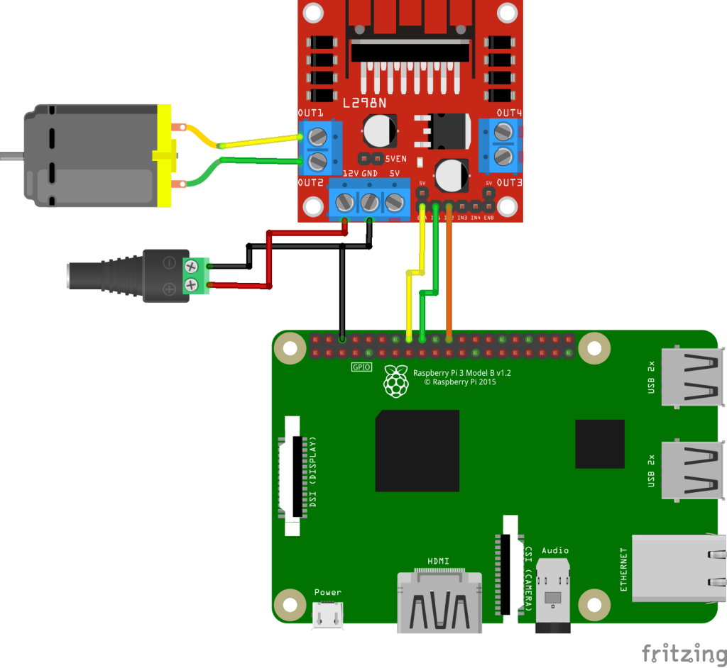

Wiring

Connect each component to the corresponding connection as listed in each row below.

5~35V DC Power ¹ DC Motor L298N GPIO
​ ENA 23 ²
​ IN1 24
​ IN2 25
+ 12V ​
– GND GND
5V 5V (Optional) ³
Pin 1 OUT1
Pin 2 OUT2
1. Use an appropriate external DC power supply that matches the voltage and current consumption of the DC motor.
2. Raspberry Pi 0~4 can use any GPIO pins, while other hardware can only use PWM output pins.
3. If the external DC power supply is less than 7V, the onboard 5V regulator will not work properly, so you must supply 5V separately to the board’s 5V terminal. In this case, you must remove the 5V-EN jumper to disable the internal regulator, otherwise voltage conflicts may occur. Conversely, if the external DC power supply is 7V or higher, the 5V-EN jumper should be inserted to use the internal regulator, and in this case, you must never connect the Raspberry Pi’s 5V to the board’s 5V terminal. Otherwise, the board or Raspberry Pi may be damaged, so be careful.


Project Links

Raspberry Pi 0~4

Raspberry Pi 5

BeagleBone Black/Green

Jetson Nano

​

찾으시는 내용이 없나요? 문의하기

문의하기

공유하기

DC Motor Control

Or copy link

Clipboard Icon
콘탠츠

ㅤ

Grablo Inc.
support@grablo.co

Site Links

  • Grablo Home
  • Grablo App

이 사이트의 모든 컨텐츠는 저작권법에 보호받는 저작물로서, 무단으로 복제, 배포하는 경우에는 저작권법에 의하여 처벌을 받을 수 있습니다. Copyright 2024 grablo.co. All Rights Reserved.