
MCP3xxx ADC
Overview
MCP3xxx analog-to-digital converter (ADC). Uses SPI interface.
Compatible Modules
| Type | ADC Output Resolution (bits) | Channels |
|---|---|---|
| MCP3002 | 10 | 2 |
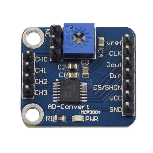
| MCP3004 | 10 | 4 |
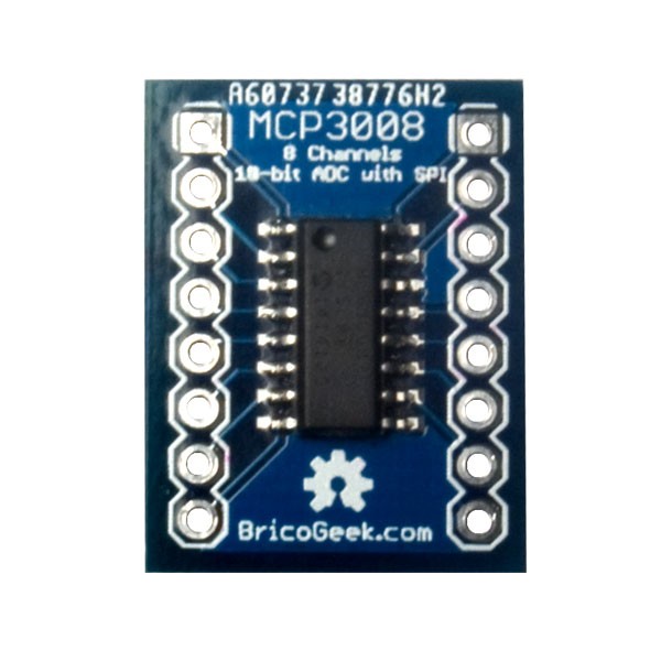
| MCP3008 | 10 | 8 |
| MCP3202 | 12 | 2 |
| MCP3204 | 12 | 4 |
| MCP3208 | 12 | 8 |
Specifications (MCP3004)
- Number of Inputs: 2, 4
- Resolution (bits): 10bit
- Input Type: Pseudo-differential, Single-ended
- Number of A/D Converters: 1
- Sampling Rate (per second): 200k
- Interface: SPI
- Voltage – Supply, Analog: 2.7V ~ 5.5V
- Voltage – Supply, Digital: 2.7V ~ 5.5V
- Operating Temperature: -40°C ~ 85°C
• For devices with 3.3V GPIO such as Raspberry Pi, BeagleBone, Jetson Nano, etc., VCC and Vref must be connected to 3.3V.
• When using MCP3008 with 5V, the Dout (MISO) pin outputs 5V which may damage the Raspberry Pi.
• If you need to connect sensors that output 0~5V, use a voltage divider to convert to 0~3.3V before connecting to MCP3xxx, or connect a level shifter to Dout (MISO) before connecting to Raspberry Pi. For detailed information, refer to here.
Supported GPIO
- Raspberry Pi 0~4
- Raspberry Pi 5
- BeagleBone Black/Green
- Jetson Nano
- FT232H, FT2232H, FT4232H
Commands
[INIT]
Enters initial configuration settings.
| Item | Type | Description |
|---|---|---|
| Module Selection | WRITE | Select the module. (MCP3002,MCP3004,MCP3008,MCP3202,MCP3204,MCP3208) |
[READ_SINGLE]
Reads the value from a single-ended channel.
| Item | Type | Description |
|---|---|---|
| Channel | WRITE | Enter the channel number to read from. |
| Value | READ | The ADC value read from the channel. |
[READ_DIFF]
Reads the value from a differential channel.
| Item | Type | Description |
|---|---|---|
| Channel * | WRITE | Enter the channel number to read from. |
| Value | READ | The ADC value read from the channel. |
* Differential channel numbers are as follows.
| Channel | Diff IN+ | Diff IN- | MCP |
|---|---|---|---|
| 0 | 0 | 1 | 3×02/3×04/3×08 |
| 1 | 1 | 0 | 3×02/3×04/3×08 |
| 2 | 2 | 3 | 3×04/3×08 |
| 3 | 3 | 2 | 3×04/3×08 |
| 4 | 4 | 5 | 3×08 |
| 5 | 5 | 4 | 3×08 |
| 6 | 6 | 7 | 3×08 |
| 7 | 7 | 6 | 3×08 |
[MAX_VALUE]
Returns the maximum possible output value of the module.
| Item | Type | Description |
|---|---|---|
| Maximum Value | READ | Returns the maximum possible output value of the module. |
[CHANNELS]
Returns the number of channels in the module.
| Item | Type | Description |
|---|---|---|
| Channel Count | READ | Returns the number of channels in the module. |
Example
Objective
Connect a potentiometer and MCP3004, and display the ADC value on a dashboard widget.
Parts
| Part | Quantity |
|---|---|
| Raspberry Pi 4 * | 1 |
| MCP3004 | 1 |
| Potentiometer | 1 |
* Other hardware can also be used. Refer to Supported GPIO.
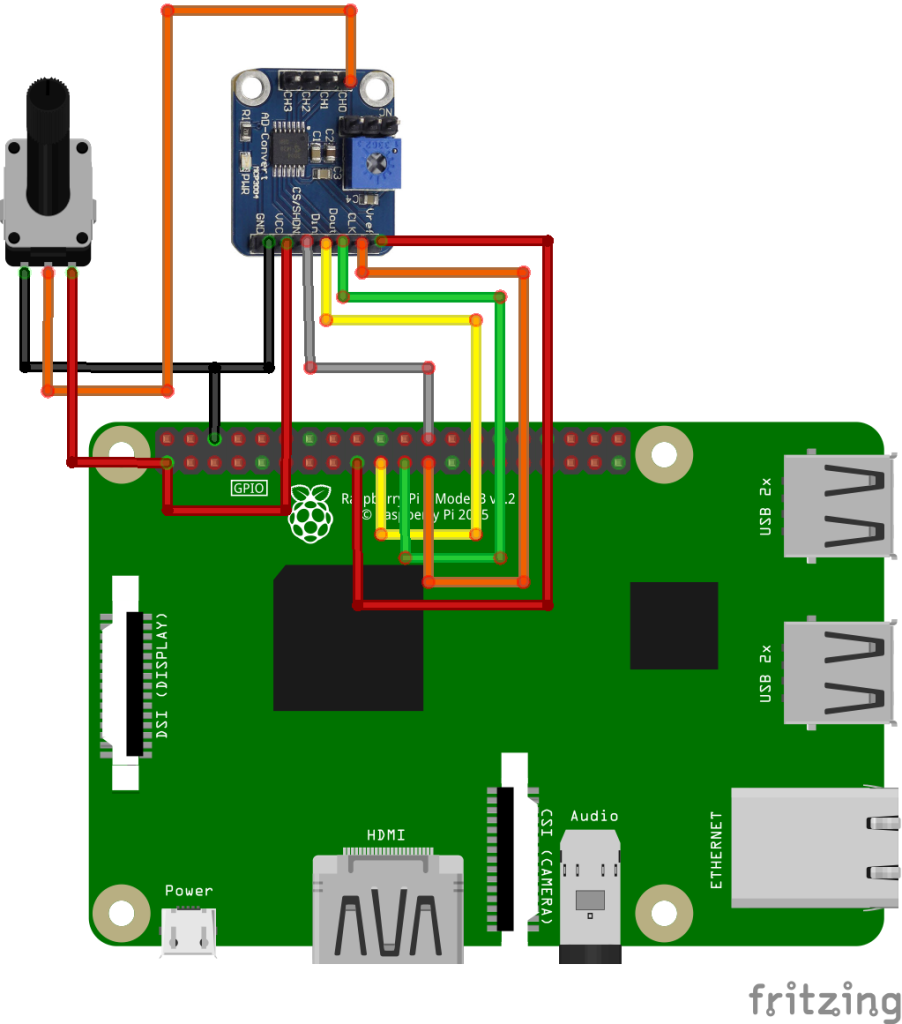
Wiring
Connect the following pins horizontally as shown.
| MCP3004 | Potentiometer | GPIO |
|---|---|---|
| VCC | Pin 1 (Left) | 3.3V |
| Vref | | 3.3V |
| GND | Pin 3 (Right) | GND |
| CLK | | 11 (SPI0 SCLK) |
| Dout | | 9 (SPI0 MISO) |
| Din | | 10 (SPI0 MOSI) |
| CS | | 8 (SPI0 CE0) |
| CH0 | Pin 2 (Center) | |
Project Link
