
NeoPixel (WS281x) LED
Overview
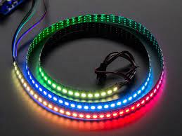
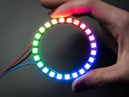
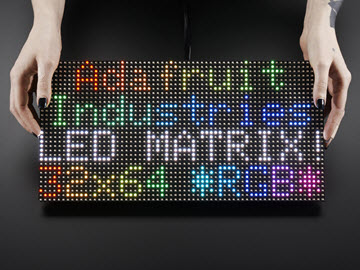
NeoPixel (WS281x) RGB LED. NeoPixel is Adafruit’s model name for products that integrate control chips like WS2811/2812 with LEDs. It has the advantage of being able to control the colors of many LEDs at high speed with a single pin. It can be configured in various shapes such as strips, rings, and matrices.
Compatible Modules
- WS281x (WS2811, WS2812…)
- SK6812
Supported GPIO
- Raspberry Pi 0~4
Commands
[INIT]
Enters initial configuration settings.
| Item | Type | Description |
|---|---|---|
| GPIO Pin * | WRITE | Enter the GPIO pin number connected to the LEDs. |
| LED Count ** | WRITE | Enter the number of LEDs connected to the pin. |
| Module Type | WRITE | Select the module type. (WS281x,SK6812) |
| Operating Frequency | WRITE | Select the module’s operating frequency. (400kHz, 800kHz) |
| RGB Order | WRITE | Select the module’s RGB order. (RGB,RBG,GRB,GBR,BRG,BGR,RGBW,RBGW,GRBW,GBRW,BRGW,BGRW) |
** Theoretically, up to 2700 LEDs can be connected to one pin. However, due to power supply and signal quality issues, the actual number of connectable LEDs may be smaller.
** When using the SPI0 MOSI pin (GPIO 10 or 38), the LED count must be set to 8 or more. Otherwise, LED colors and positions may be displayed differently than configured.
| GPIO Number | Name | Raspberry Pi Model |
|---|---|---|
| 10 | SPI0 MOSI | All models (except 5) |
| 12 | PWM0 | All models (except A, B, 5) |
| 13 | PWM1 | All models (except A, B, 5) |
| 18 | PWM0 | All models (except 5) |
| 19 | PWM1 | All models (except A, B, 5) |
| 38 | SPI0 MOSI | Compute module |
| 40 | PWM0 | Compute module |
| 41 | PWM1 | Compute module |
| 45 | PWM1 | Compute module |
| 52 | PWM0 | Compute module |
| 53 | PWM1 | Compute module |
[SET_BRIGHTNESS]
Sets the brightness of the LEDs.
| Item | Type | Description |
|---|---|---|
| Brightness | WRITE | Controls the brightness of all connected LEDs. (0~255) |
[SET_PIXEL_COLOR]
Sets the color of an LED at a specific position. The SHOW command must be executed for the color to be displayed.
| Item | Type | Description |
|---|---|---|
| Position | WRITE | The position of the LED to set the color for. Starts from 0. |
| Color Type | WRITE | Select the type of color to set. (RGB or HSV) |
Color Type: RGB
| Item | Type | Description |
|---|---|---|
| R | WRITE | Enter the R component of the color. (0~255) |
| G | WRITE | Enter the G component of the color. (0~255) |
| B | WRITE | Enter the B component of the color. (0~255) |
| W | WRITE | Enter the W component of the color. (0~255, RGBW type LEDs only) |
Color Type: HSV
| Item | Type | Description |
|---|---|---|
| H | WRITE | Enter the H (Hue) component of the color. (0~360) |
| S | WRITE | Enter the S (Saturation) component of the color. (0~100) |
| V | WRITE | Enter the V (Value, brightness) component of the color. (0~100) |
[SET_PIXELS_COLOR]
Sets the color of multiple LEDs. The SHOW command must be executed for the colors to be displayed.
| Item | Type | Description |
|---|---|---|
| Start Position | WRITE | The starting position of the LEDs to set the color for. The first LED position is 0. |
| Count | WRITE | Enter the number of LEDs to set the color for. |
| Color Type | WRITE | Select the type of color to set. |
Color Type: RGB
| Item | Type | Description |
|---|---|---|
| R | WRITE | Enter the R component of the color. (0~255) |
| G | WRITE | Enter the G component of the color. (0~255) |
| B | WRITE | Enter the B component of the color. (0~255) |
| W | WRITE | Enter the W component of the color. (0~255, RGBW type LEDs only) |
Color Type: HSV
| Item | Type | Description |
|---|---|---|
| H | WRITE | Enter the H (Hue) component of the color. (0~360) |
| S | WRITE | Enter the S (Saturation) component of the color. (0~100) |
| V | WRITE | Enter the V (Value, brightness) component of the color. (0~100) |
[SHOW]
Displays the configured colors on the LEDs.
[CLEAR]
Turns off all LEDs.
Example
Objective
When the dashboard button is pressed, light up the NeoPixels one by one in rainbow colors at 0.1-second intervals.
Parts
| Part | Quantity |
|---|---|
| Raspberry Pi 4 * | 1 |
| WS2812 (16 LED) | 1 |
| 5V DC Power Supply | 1 |
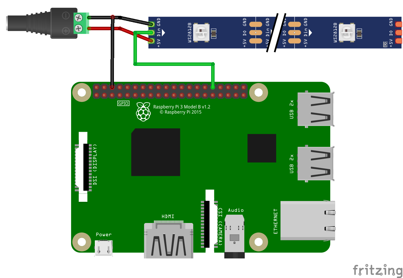
Wiring
Connect the following pins horizontally to each other.
| 5V DC Power ** | WS2812 LED | GPIO |
|---|---|---|
| + | +5V | |
| | Din | 12 * |
| – | GND | GND |
** Use an appropriate external DC Power Supply considering the voltage and current consumption of the LEDs.
Project Link
Limitations
PWM
When using NeoPixels with PWM0, PWM1 pins, conflicts may occur with Raspberry Pi audio, causing improper operation. This is because audio also uses the Raspberry Pi’s hardware PWM. Therefore, in this case, you can use NeoPixels normally through PWM pins by disabling Raspberry Pi audio as shown below. However, in this case, the onboard audio (3.5mm audio jack on the side) cannot be used, and audio output through HDMI or USB sound cards must be used.
Enter the following command in the Raspberry Pi terminal to create a file.
sudo nano /etc/modprobe.d/snd-blacklist.confAdd the following content to the end of the file.
blacklist snd_bcm2835Press Ctrl + O -> Enter -> Ctrl + X to save and exit the file.
Enter the following command to reboot the Raspberry Pi.
sudo rebootSPI
When using the SPI-MOSI pin with a large number of NeoPixels (approximately 340 or more), the SPI transfer buffer size must be increased.
Enter the following command in the Raspberry Pi terminal to edit the file.
sudo nano /boot/cmdline.txtAdd the following content to the end of the file.
spidev.bufsiz=32768Press Ctrl + O -> Enter -> Ctrl + X to save and exit the file.
Enter the following command to reboot the Raspberry Pi.
sudo rebootFor Raspberry Pi 3 and 4, additional modifications are required as shown below.
Enter the following command in the terminal to edit the file.
sudo nano /boot/config.txtAdd the following to the end.
- Raspberry Pi 3
core_freq=250- Raspberry Pi 4
core_freq=500

core_freq_min=500
Press Ctrl + O -> Enter -> Ctrl + X to save and exit the file.
Enter the following command to reboot the Raspberry Pi.
sudo reboot
