
SSD1306 0.96-inch Monochrome OLED Display
Overview
A 0.96-inch monochrome OLED display using the SSD1306 chipset. It uses I2C or SPI interface.

Compatible Modules
- 128×32 OLED
- 128×64 OLED
- 96×16 OLED
Specifications
- 0.91-inch OLED with White Display color.
- 128×32 or 128×64 or 96×16 resolution.
- OLED display without backlight needs.
- Low power dissipation.
- Wide viewing angle at least 160 degrees.
- Voltage: 3.0V-5.0V.
Supported GPIO
- Raspberry Pi 0~4
- Raspberry Pi 5
- BeagleBone Black/Green
- Jetson Nano
- FT232H, FT2232H, FT4232H
- MCP2221
Commands
[INIT]
Enters initial configuration settings.
| Item | Type | Description |
|---|---|---|
| Type | WRITE | Select the OLED size. (128×32, 128×64, 96×16) |
| RESET Pin | WRITE | GPIO pin number to connect for hardware Reset function. If not using this function, enter -1 and connect RESET pin to 3.3V. |
| D/C Pin | WRITE | Enter the GPIO pin number to connect to the D/C (Data/Command) pin. Only displayed when using SPI interface. |
[SET_ROTATION]
Sets the display orientation.
| Item | Type | Description |
|---|---|---|
| Rotation | WRITE | Select the direction for displaying text, shapes, etc. (0°, 90°, 180°, 270°) |
[DISPLAY]
Displays the configured content on the display.
[CLEAR]
Clears all configured content from the display. Since only the buffer memory is cleared, you must execute the DISPLAY command to clear the content shown on the display.
[INVERT_DISPLAY]
Sets whether to invert the display colors.
| Item | Type | Description |
|---|---|---|
| Invert | WRITE | If true, displays inverted colors; if false, displays original colors. |
[SET_CURSOR]
Specifies the position to write text on the display.
| Item | Type | Description |
|---|---|---|
| Position (x) | WRITE | Enter the starting position (x) of the text. The leftmost pixel of the display is 0, increasing to the right. |
| Position (y) | WRITE | Enter the starting position (y) of the text. The topmost pixel of the display is 0, increasing downward. |
[PRINT_TEXT]
Sets text on the display. You must execute the DISPLAY command to show it on the display.
| Item | Type | Description |
|---|---|---|
| Text | WRITE | Enter the text to display. |
| Size | WRITE | Enter the text size. (1~255) |
| Word Wrap | WRITE | Sets whether to automatically wrap lines when text length exceeds the horizontal display range. |
| Text Color | WRITE | Select the text color. BLACK means pixel OFF color, WHITE means pixel ON color. (BLACK, WHITE) |
| Background Color | WRITE | Select the background color. BLACK means pixel OFF color, WHITE means pixel ON color. (BLACK, WHITE) |
[DRAW_PIXEL]
Sets a pixel at the specified position on the display. You must execute the DISPLAY command to show it on the display.
| Item | Type | Description |
|---|---|---|
| Position (x) | WRITE | Enter the pixel position (x). The leftmost pixel of the display is 0, increasing to the right. |
| Position (y) | WRITE | Enter the pixel position (y). The topmost pixel of the display is 0, increasing downward. |
| Color | WRITE | Select the pixel color. BLACK means pixel OFF color, WHITE means pixel ON color. (BLACK, WHITE) |
[DRAW_LINE]
Sets a straight line on the display. You must execute the DISPLAY command to show it on the display.
| Item | Type | Description |
|---|---|---|
| Start Point (x) | WRITE | Enter the starting position (x) of the line. The leftmost pixel of the display is 0, increasing to the right. |
| Start Point (y) | WRITE | Enter the starting position (y) of the line. The topmost pixel of the display is 0, increasing downward. |
| End Point (x) | WRITE | Enter the ending position (x) of the line. The leftmost pixel of the display is 0, increasing to the right. |
| End Point (y) | WRITE | Enter the ending position (y) of the line. The topmost pixel of the display is 0, increasing downward. |
| Color | WRITE | Select the line color. BLACK means pixel OFF color, WHITE means pixel ON color. (BLACK, WHITE) |
[DRAW_TRIANGLE]
Sets a hollow triangle on the display. You must execute the DISPLAY command to show it on the display.
| Item | Type | Description |
|---|---|---|
| Point 1 (x) | WRITE | Enter the position (x) of triangle point 1. The leftmost pixel of the display is 0, increasing to the right. |
| Point 1 (y) | WRITE | Enter the position (y) of triangle point 1. The topmost pixel of the display is 0, increasing downward. |
| Point 2 (x) | WRITE | Enter the position (x) of triangle point 2. The leftmost pixel of the display is 0, increasing to the right. |
| Point 2 (y) | WRITE | Enter the position (y) of triangle point 2. The topmost pixel of the display is 0, increasing downward. |
| Point 3 (x) | WRITE | Enter the position (x) of triangle point 3. The leftmost pixel of the display is 0, increasing to the right. |
| Point 3 (y) | WRITE | Enter the position (y) of triangle point 3. The topmost pixel of the display is 0, increasing downward. |
| Color | WRITE | Select the triangle color. BLACK means pixel OFF color, WHITE means pixel ON color. (BLACK, WHITE) |
[FILL_TRIANGLE]
Sets a filled triangle on the display. You must execute the DISPLAY command to show it on the display.
| Item | Type | Description |
|---|---|---|
| Point 1 (x) | WRITE | Enter the position (x) of triangle point 1. The leftmost pixel of the display is 0, increasing to the right. |
| Point 1 (y) | WRITE | Enter the position (y) of triangle point 1. The topmost pixel of the display is 0, increasing downward. |
| Point 2 (x) | WRITE | Enter the position (x) of triangle point 2. The leftmost pixel of the display is 0, increasing to the right. |
| Point 2 (y) | WRITE | Enter the position (y) of triangle point 2. The topmost pixel of the display is 0, increasing downward. |
| Point 3 (x) | WRITE | Enter the position (x) of triangle point 3. The leftmost pixel of the display is 0, increasing to the right. |
| Point 3 (y) | WRITE | Enter the position (y) of triangle point 3. The topmost pixel of the display is 0, increasing downward. |
| Color | WRITE | Select the triangle color. BLACK means pixel OFF color, WHITE means pixel ON color. (BLACK, WHITE) |
[DRAW_RECT]
Sets a hollow rectangle on the display. You must execute the DISPLAY command to show it on the display.
| Item | Type | Description |
|---|---|---|
| Start Point (x) | WRITE | Enter the starting point (top-left) position (x) of the rectangle. The leftmost pixel of the display is 0, increasing to the right. |
| Start Point (y) | WRITE | Enter the starting point (top-left) position (y) of the rectangle. The topmost pixel of the display is 0, increasing downward. |
| Width | WRITE | Enter the width of the rectangle. |
| Height | WRITE | Enter the height of the rectangle. |
| Color | WRITE | Select the rectangle color. BLACK means pixel OFF color, WHITE means pixel ON color. (BLACK, WHITE) |
[FILL_RECT]
Sets a filled rectangle on the display. You must execute the DISPLAY command to show it on the display.
| Item | Type | Description |
|---|---|---|
| Start Point (x) | WRITE | Enter the starting point (top-left) position (x) of the rectangle. The leftmost pixel of the display is 0, increasing to the right. |
| Start Point (y) | WRITE | Enter the starting point (top-left) position (y) of the rectangle. The topmost pixel of the display is 0, increasing downward. |
| Width | WRITE | Enter the width of the rectangle. |
| Height | WRITE | Enter the height of the rectangle. |
| Color | WRITE | Select the rectangle color. BLACK means pixel OFF color, WHITE means pixel ON color. (BLACK, WHITE) |
[DRAW_ROUND_RECT]
Sets a hollow rounded rectangle on the display. You must execute the DISPLAY command to show it on the display.
| Item | Type | Description |
|---|---|---|
| Start Point (x) | WRITE | Enter the starting point (top-left) position (x) of the rectangle. The leftmost pixel of the display is 0, increasing to the right. |
| Start Point (y) | WRITE | Enter the starting point (top-left) position (y) of the rectangle. The topmost pixel of the display is 0, increasing downward. |
| Width | WRITE | Enter the width of the rectangle. |
| Height | WRITE | Enter the height of the rectangle. |
| Corner Radius | WRITE | Enter the radius of the rectangle corners. |
| Color | WRITE | Select the rectangle color. BLACK means pixel OFF color, WHITE means pixel ON color. (BLACK, WHITE) |
[FILL_ROUND_RECT]
Sets a filled rounded rectangle on the display. You must execute the DISPLAY command to show it on the display.
| Item | Type | Description |
|---|---|---|
| Start Point (x) | WRITE | Enter the starting point (top-left) position (x) of the rectangle. The leftmost pixel of the display is 0, increasing to the right. |
| Start Point (y) | WRITE | Enter the starting point (top-left) position (y) of the rectangle. The topmost pixel of the display is 0, increasing downward. |
| Width | WRITE | Enter the width of the rectangle. |
| Height | WRITE | Enter the height of the rectangle. |
| Corner Radius | WRITE | Enter the radius of the rectangle corners. |
| Color | WRITE | Select the rectangle color. BLACK means pixel OFF color, WHITE means pixel ON color. (BLACK, WHITE) |
[DRAW_CIRCLE]
Sets a hollow circle on the display. You must execute the DISPLAY command to show it on the display.
| Item | Type | Description |
|---|---|---|
| Center (x) | WRITE | Enter the center point position (x) of the circle. The leftmost pixel of the display is 0, increasing to the right. |
| Center (y) | WRITE | Enter the center point position (y) of the circle. The topmost pixel of the display is 0, increasing downward. |
| Radius | WRITE | Enter the radius of the circle. |
| Color | WRITE | Select the circle color. BLACK means pixel OFF color, WHITE means pixel ON color. (BLACK, WHITE) |
[FILL_CIRCLE]
Sets a filled circle on the display. You must execute the DISPLAY command to show it on the display.
| Item | Type | Description |
|---|---|---|
| Center (x) | WRITE | Enter the center point position (x) of the circle. The leftmost pixel of the display is 0, increasing to the right. |
| Center (y) | WRITE | Enter the center point position (y) of the circle. The topmost pixel of the display is 0, increasing downward. |
| Radius | WRITE | Enter the radius of the circle. |
| Color | WRITE | Select the circle color. BLACK means pixel OFF color, WHITE means pixel ON color. (BLACK, WHITE) |
[FILL_SCREEN]
Fills the entire display. You must execute the DISPLAY command to show it on the display.
| Item | Type | Description |
|---|---|---|
| Color | WRITE | Select the fill color. BLACK means pixel OFF color, WHITE means pixel ON color. (BLACK, WHITE) |
[DRAW_BITMAP]
Sets a BMP format image file on the display. You must execute the DISPLAY command to show it on the display.
| Item | Type | Description |
|---|---|---|
| File Path * | WRITE | Enter the local path of the image file. (e.g., /home/pi/test.bmp) |
| Start Point (x) | WRITE | Enter the top-left position (x) of the image. The leftmost pixel of the display is 0, increasing to the right. |
| Start Point (y) | WRITE | Enter the top-left position (y) of the image. The topmost pixel of the display is 0, increasing downward. |
* Color images are automatically converted to black and white.
[START_SCROLL]
Scrolls the content displayed on the display.
| Item | Type | Description |
|---|---|---|
| Direction | WRITE | Select the scroll direction. (Left, Right, Diagonal Left, Diagonal Right) |
| Start Row | WRITE | Enter the start row. The topmost row is 0. (0~7) |
| End Row | WRITE | Enter the end row. The topmost row is 0. (0~7) |
[STOP_SCROLL]
Stops scrolling.
[DIM]
Reduces the brightness of the display.
| Item | Type | Description |
|---|---|---|
| Dim | WRITE | If true, reduces brightness; if false, returns to original brightness. |
Example
Objective
Display the following alternately at 1-second intervals:
- “Hello Grablo” text
- A filled circle with center at (64, 32) and radius of 20
- BMP image
Parts
| Part | Quantity |
|---|---|
| Raspberry Pi 4 * | 1 |
| SSD1306 OLED | 1 |
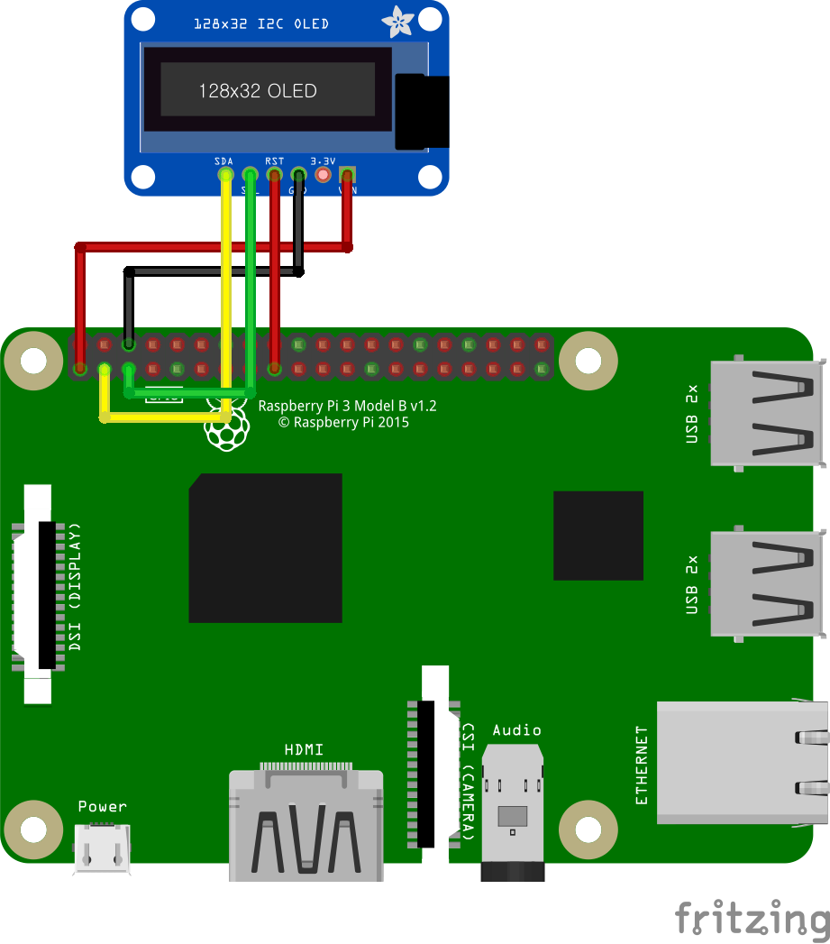
Wiring (I2C)
Connect the following pins horizontally to each other.
| SSD1306 OLED | GPIO |
|---|---|
| VIN | 3.3V |
| GND | GND |
| SCL | 3 (I2C1 SCL) |
| SDA | 2 (I2C1 SDA) |
| RESET (RST) | 3.3V * |
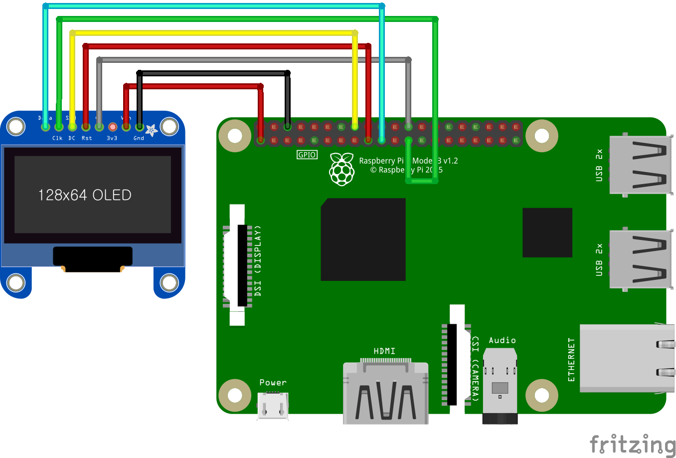
Wiring (SPI)
Connect the following pins horizontally to each other.
| SSD1306 OLED | GPIO |
|---|---|
| VIN | 3.3V |
| GND | GND |
| CS | 8 (SPI0 CE0) |
| DATA | 10 (SPI0 MOSI) |
| CLK | 11 (SPI0 SCLK) |
| RESET (RST) | 3.3V * |
| D/C | 23 ** |
** Any GPIO pins can be used.
Project Links
SSD1306 SPI
