
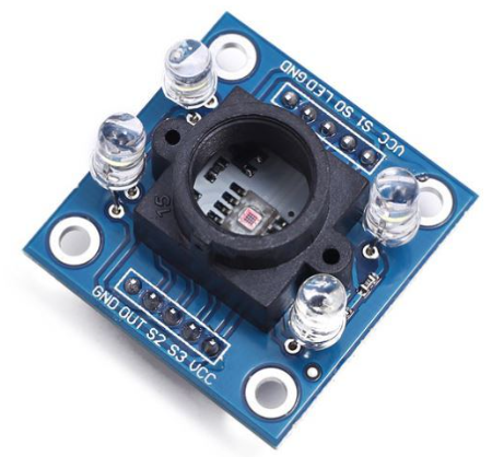
TCS3200 RGB Color Sensor
Overview
An RGB color sensor capable of detecting the color of objects.
Specifications
- Power: 2.7V to 5.5V
- Interface:Digital TTL
- High-Resolution Conversion of Light Intensity to Frequency
- Programmable Color and Full-Scale Output Frequency
- Power Down Feature
Supported GPIO
- Raspberry Pi 0~4
Commands
[INIT]
Enters initial configuration settings.
| Item | Type | Description |
|---|---|---|
| OUT Pin | WRITE | Enter the GPIO pin to connect to the OUT pin. |
| S2 Pin | WRITE | Enter the GPIO pin to connect to the S2 pin. |
| S3 Pin | WRITE | Enter the GPIO pin to connect to the S3 pin. |
| S0 Pin (Optional) * | WRITE | Enter the GPIO pin to connect to the S0 pin. |
| S1 Pin (Optional) * | WRITE | Enter the GPIO pin to connect to the S1 pin. |
| OE Pin (Optional) ** | WRITE | Enter the GPIO pin to connect to the OE pin. |
* Pin for setting output frequency scaling. This is an optional input item; when not entered, connect S0 to 3.3V and S1 to GND.
** Pin for setting Output Enable. This is an optional input item; when not entered, do not connect.
** Pin for setting Output Enable. This is an optional input item; when not entered, do not connect.
[START]
Starts the module. Calibration levels can be obtained through calibration. Once the module is started, it runs continuously in the background, so this command only needs to be used once.
| Item | Type | Description |
|---|---|---|
| Sample Size | WRITE | Number of samples to measure for color detection. (10~100) |
| Frequency Scaling | WRITE | Select the resolution (Frequency Scaling). Only applied when S0 and S1 pins are entered in the INIT command; otherwise ignored. (Off, 2%, 20%, 100%) |
| Measurement Time | WRITE | Time to measure color. (0.1~2 seconds) |
| Calibration Level R (Black) * | WRITE | Calibration Level R value for black objects. |
| Calibration Level G (Black) * | WRITE | Calibration Level G value for black objects. |
| Calibration Level B (Black) * | WRITE | Calibration Level B value for black objects. |
| Calibration Level R (White) * | WRITE | Calibration Level R value for white objects. |
| Calibration Level G (White) * | WRITE | Calibration Level G value for white objects. |
| Calibration Level B (White) * | WRITE | Calibration Level B value for white objects. |
* Can be obtained through the CALIBRATION command.
[CALIBRATION]
Performs calibration using black or white objects.
| Item | Type | Description |
|---|---|---|
| R | READ | R component of the color. |
| G | READ | G component of the color. |
| B | READ | B component of the color. |
[GET_RGB]
Detects RGB color.
| Item | Type | Description |
|---|---|---|
| R | READ | R component of the color. |
| G | READ | G component of the color. |
| B | READ | B component of the color. |
Example
Objective
Display the R, G, B values of an object’s color on the dashboard widget.
Calibration must be performed to display proper values. The calibration method is as follows:
- RUN mode
- Place a white object near the sensor and turn ON the dashboard calibration switch.
- Record the displayed R, G, B values separately and turn OFF the calibration switch. (Turn ON/OFF multiple times to record stable values)
- Place a black object near the sensor and turn ON the dashboard calibration switch.
- Record the displayed R, G, B values separately and turn OFF the calibration switch. (Turn ON/OFF multiple times to record stable values)
- STOP mode
- Go to Settings → IO Device → Edit TCS3200 → Enter the recorded values in the Calibration level R, G, B of the START initial command.
- RUN mode
Parts
| Part | Quantity |
|---|---|
| Raspberry Pi 4 * | 1 |
| TCS3200 | 1 |
* Other hardware can also be used. Refer to Supported GPIO.
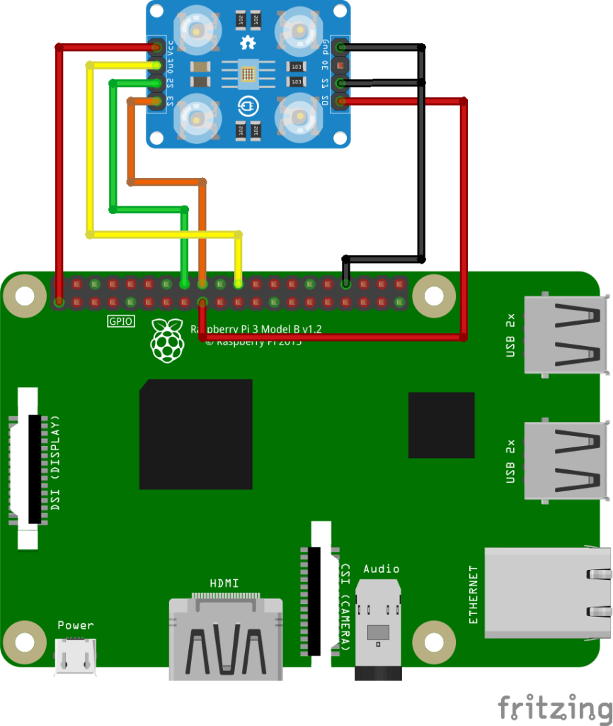
Wiring
Connect the following pins horizontally to each other.
| TCS3200 | GPIO |
|---|---|
| VCC | 3.3V |
| S2 | 23 * |
| S3 | 24 * |
| OUT | 25 * |
| GND | GND |
| S0 | 3.3V |
| S1 | GND |
| OE ** | Not Connected |
| LED ** | 3.3V |
* Any GPIO pins can be used.
** May not exist depending on the module.
** May not exist depending on the module.
Project Link
