
Analog to Digital Converter (ADC)
Introduction
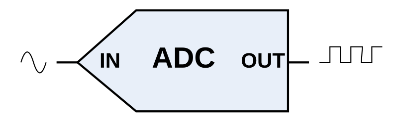
Analog-to-Digital Converter (ADC) library. Can only be used if the hardware has ADC pins.
Supported GPIO
- BeagleBone Black/Green
- MCP2221
- NUMATO USB-GPIO (8~128CH)
Commands
[INIT]
Enters initial configuration settings.
| Item | Type | Description |
|---|---|---|
| ADC Pin | WRITE | Select the ADC input pin. |
[READ_VALUE]
Reads the ADC conversion value.
| Item | Type | Description |
|---|---|---|
| Conversion Value * | READ | The converted value of the input voltage. |
* The input voltage range and resolution vary depending on the hardware. Please refer to the specifications of each hardware.
Example (BeagleBone Black)
Objective
Connect a variable resistor to the ADC pin and display the conversion value on dashboard widgets.
Parts
| Part | Quantity |
|---|---|
| BeagleBone Black * | 1 |
| Variable Resistor | 1 |
* Other hardware can also be used. Refer to Supported GPIO.
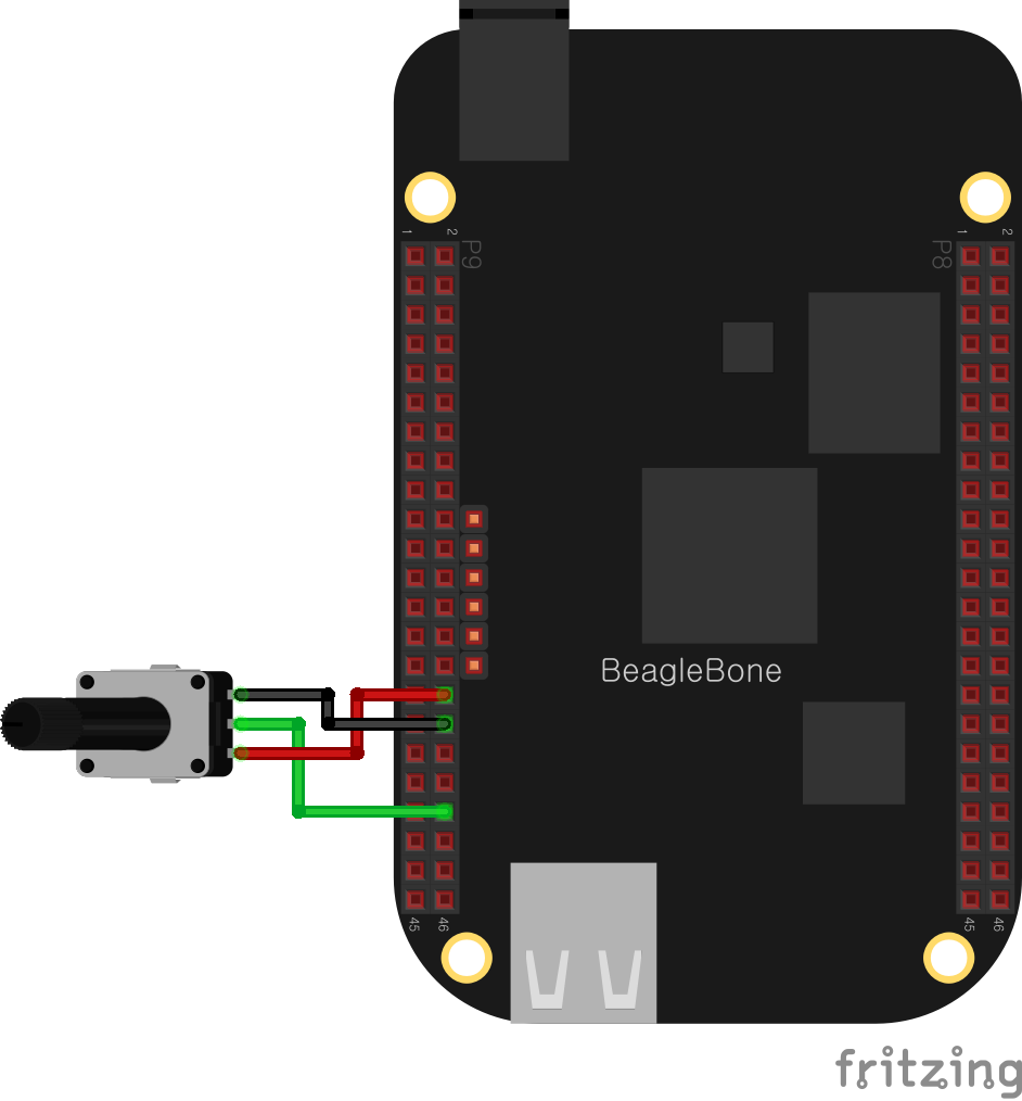
Wiring
Connect the following pins horizontally to each other.
| Variable Resistor | GPIO |
|---|---|
| Pin 1 (Left) | VDD_ADC |
| Pin 3 (Right) | GND_ADC |
| Pin 2 (Center) | AIN1 * |
* AIN0~AIN6 pins can be used.
Project Links
