
GPIO
GPIO stands for General Purpose Input/Output, which refers to a general-purpose input/output interface. These are pins used to control various external devices such as push buttons, LEDs, and sensors.
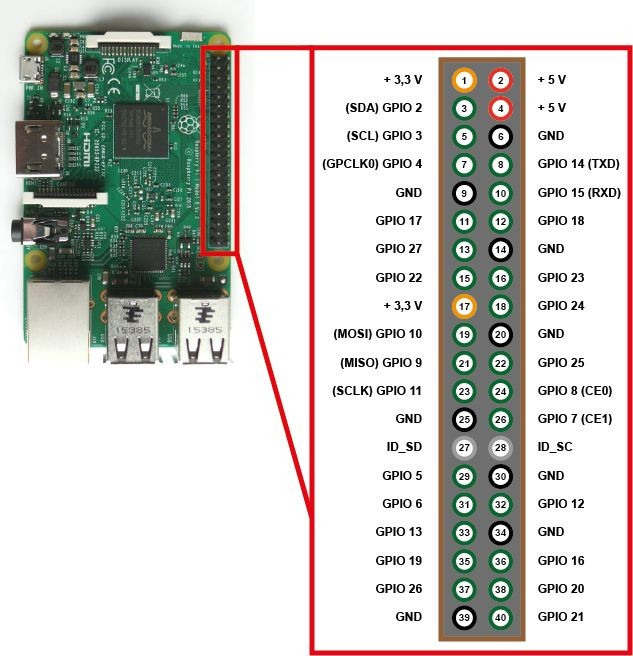
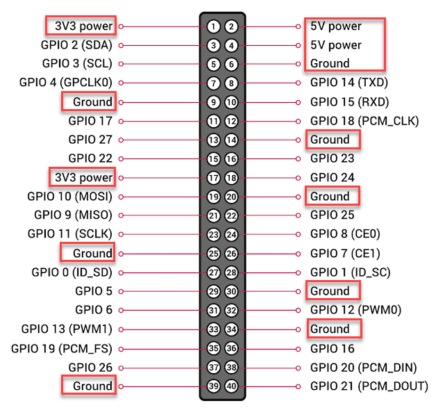
All currently released Raspberry Pi models provide 40-pin GPIO, and the function of each pin is the same regardless of the model. There are two methods for numbering pins: one based on the connector pin numbers (Physical/Board) and another based on the Broadcom CPU channel numbers (GPIO/BCM).
All pin numbers used in Grablo are based on GPIO/BCM. Therefore, care must be taken not to confuse GPIO pin numbers with connector pin numbers.
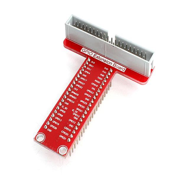
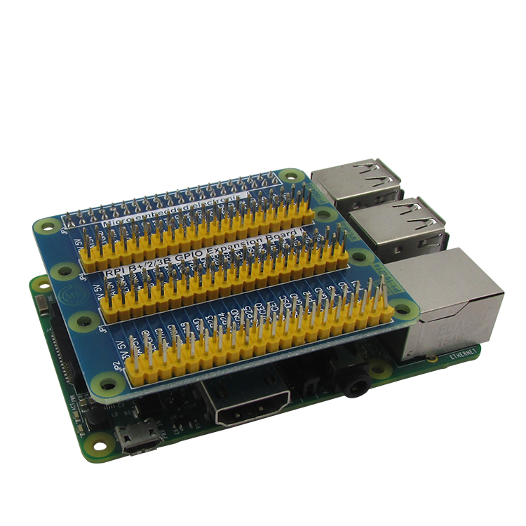
You can connect to GPIO more conveniently by using GPIO expansion boards available in the market.
3.3V, 5V, GND(Ground)
Pins for supplying power to external devices.
– 3.3V pin: approximately 800mA
– 5V pin: approximately 2.5A minus the Raspberry Pi’s own current consumption (including camera, USB, etc.) and 3.3V pin current consumption
For external devices with high current consumption such as motors and many LEDs, it is recommended to supply power from a separate external power source.
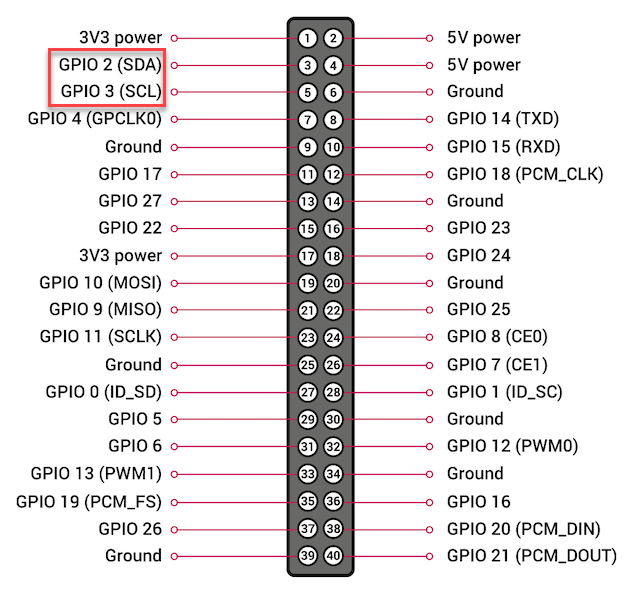
Hardware I2C Pins
GPIO 2 and 3 are pins for I2C communication. They can also be used as general digital input/output pins.
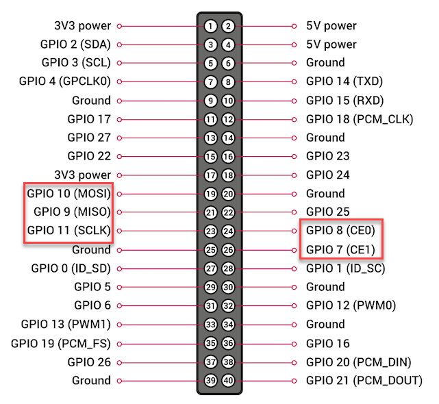
Hardware SPI Pins
GPIO 7, 8, 9, 10, and 11 are pins for SPI communication. They can also be used as general digital input/output pins.
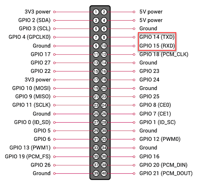
Serial (UART) Communication Pins
GPIO 14 and 15 are pins for serial (UART) communication. They can also be used as general digital input/output pins.
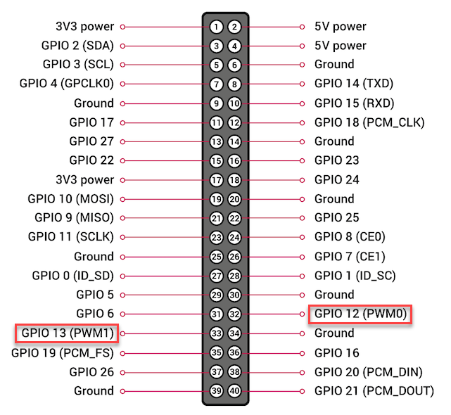
Hardware PWM Pins
GPIO 12 and 13 are pins for hardware PWM output. They can also be used as general digital input/output pins.
Other GPIO Pins
Pins for general digital input/output.
For more detailed information about each pin, please refer to https://pinout.xyz/.
