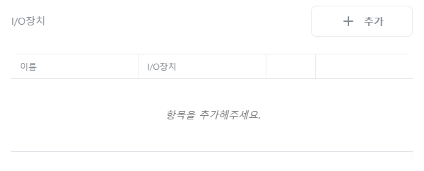
Grablo Help Grablo Help
  • User Manual
  • Tips
  • News
  • Go to
    • Grablo Home
    • Grablo App
  • 한국어
Grablo Help Grablo Help
문의하기
Grablo Help Grablo Help
  • User Manual
  • Tips
  • News
  • Go to
    • Grablo Home
    • Grablo App
  • 한국어
loading
  1. Home
  2. User Manuals
  3. Setting
  4. I/O Device
Updated on August 13, 2025

User Manuals

  • Folder icon closed Folder open iconQuick Start Guide
    • Grablo!
    • Basic Concepts
  • Folder icon closed Folder open iconProject
    • General
    • Sharing Project
  • Folder icon closed Folder open iconLogic
    • Logic
    • Control Group
    • Control
    • Condition Group
    • Action Group
    • Condition
      • General
      • Type
        • Always Met
        • Once Met
        • Variable Comparison
        • Schedule
        • Time Range
        • Time Interval
        • Condition Reference
        • Action Reference
        • Change Detection
        • Custom Condition
    • Action
      • General
      • Type
        • Write Variable
        • I/O Device Control
        • Time Delay
        • Timer
        • Display Image
        • Play Media
        • Synthesizer
        • Audio Recording
        • Audio Transform
        • Shell Command
        • Speech-to-Text
        • Text-to-Speech
        • File System
        • Read/Write File
        • Database
        • HTTP Communication
        • MQTT Communication
        • OPC UA Communication
        • Modbus Communication
        • Send Email
        • Telegram Message
        • User Defined Communication
        • PID Control
        • Statistics
        • Collection
        • Custom Action
  • Folder icon closed Folder open iconDashboard
    • General
    • Widgets
  • Folder icon closed Folder open iconSetting
    • GPIO
    • Variables
    • I/O Device
    • File Editor
    • Collection
    • Timer
    • Image Viewer
    • Audio Transfrom
    • Media Player
    • Synthesizer
    • Text-to-Speech
    • Speech-to-Text
    • Audio Recorder
    • MQTT Client
    • OPC UA Client
    • Modbus
    • Email Client
    • Telegram Bot
    • Database
    • User Defined Communication
    • PID Control
    • Statistics
  • Folder icon closed Folder open iconI/O Device
    • DS18B20 Digital Temperature Sensor
    • MAX31865 RTD Temperature Sensor
    • TinyGPS++ GPS Library
    • BMP180 Digital Pressure and Temperature Sensor
    • AHTx0 Temperature and Humidity Sensor
    • SHT2x Temperature and Humidity Sensor
    • Servo Motor Control
    • PWM Signal Output
    • PWM Signal Monitoring
    • Hardware PWM Signal Output
    • LED Control
    • Push Button Input
    • Digital I/O
    • Stepper Motor Control
    • High Speed Counter
    • ADS1x15 ADC
    • ADXL345 3-Axis Accelerometer
    • BME280 Temperature, Humidity, Pressure Sensor
    • BMP280 Temperature, Pressure Sensor
    • MLX90614 Infrared Temperature Sensor
    • MCP4725 DAC
    • QMC5883L 3-Axis Magnetometer
    • SHT31 Digital Temperature and Humidity Sensor
    • TCS34725 RGB Color Sensor
    • VEML6070 UV Sensor
    • BH1750 Digital Light Intensity Sensor
    • DS3231 RTC High-Precision Real-Time Clock
    • MPU-9250 9-Axis IMU Sensor
    • CCS811 Carbon Dioxide and TVOC Air Quality Sensor
    • VL53L0X ToF Laser Distance Sensor
    • TFmini Plus(S) LiDAR Distance Sensor
    • MAX7219 8-Digit 7-Segment Display
    • PCF8574 LCD Display Driver
    • HC-SR04 Ultrasonic Distance Sensor
    • LED Brightness Control
    • RGB LED Color Control
    • DC Motor Control
    • AT24C256 EEPROM Memory
    • DHTxx Temperature and Humidity Sensor
    • MCP3xxx ADC
    • LCD Display Driver (MCP23008, MCP23017)
    • MFRC522 RFID Reader
    • Passive Buzzer
    • NeoPixel (WS281x) LED
    • Infrared (IR) Receiver
    • NeoPixel Matrix
    • ST77xx TFT Color LCD
    • ILI9341 TFT Color LCD
    • SSD1306 0.96-inch Monochrome OLED Display
    • SH1106 1.3-inch Monochrome OLED Display
    • MAX7219 8×8 LED Dot Matrix
    • HT16K33 4-Digit 7-Segment Display
    • HX711 Load Cell 24-bit AD Converter
    • TCS3200 RGB Color Sensor
    • MPU6050 6-Axis Gyro Accelerometer
    • TM1637 4-Digit 7-Segment Display
    • PM2008(M) Particulate Matter Sensor
    • PMS x003 Particulate Matter Sensor
    • MAX30102 SpO2 and Heart Rate Sensor
    • AS608, FPM10A Fingerprint Sensor
    • TTP229 Capacitive 16-Key Touch Keypad
    • 4×4 Keypad Matrix
    • Analog to Digital Converter (ADC)
    • Digital to Analog Converter (DAC)
    • RPM Monitor
    • PCA9685 16-Channel 12-Bit PWM Servo Driver
    • INA219 DC Current Sensor
    • VL6180X ToF Distance Sensor
    • Custom Digital Waveform Output
    • NRF24L01 2.4GHz RF Module
  • Folder icon closed Folder open iconBlock Coding
    • General
    • Blocks
      • Values
      • Logic
      • Loop
      • Math
      • Date/Time
      • Text
      • Byte Array
      • List
      • Type Conversion
      • Unit Conversion
      • Science
      • Bit/Byte
      • Complex Numbers/Vectors
      • JSON
      • XML
      • Local Variables
      • Local Functions
  • Folder icon closed Folder open iconConnect & Run
    • Hardware and Operating System
    • Grablo Package Installation
    • Connect and Run

I/O Device

Estimated reading: 3 minutes 381 views

This is the I/O device configuration used in [Action] -> [I/O Device Control].


Add

Click the [+Add] button.
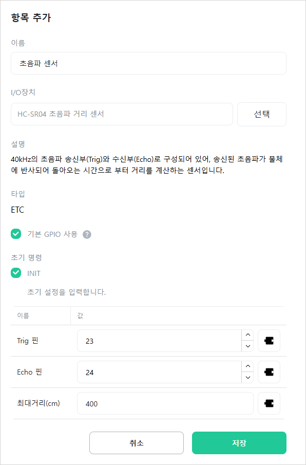

[Name]

Enter the name of the I/O device. You can use any name.
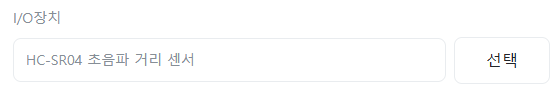

[I/O Device]

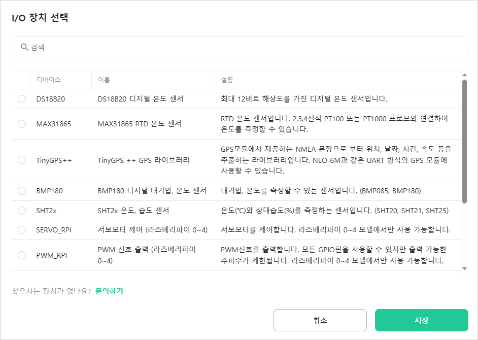
Click [Select] to choose the I/O device to use.


Select the device to use. You can use the search function to quickly find devices.


[Description]

Description of the selected device.


[Type]

Type of the selected device. One of the following types will be displayed: I2C, SPI, UART, 1-WIRE, or ETC.


[Use Default GPIO]

Select whether to use the default GPIO of the controller hardware.


[GPIO Selection]

When not using default GPIO, select the Extended GPIO to use. This is displayed only when [Use Default GPIO] is unchecked.


[Interface]

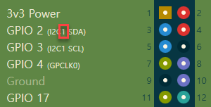
Select the I2C or SPI communication interface. This is displayed only when using default GPIO and [Type] is “I2C” or “SPI”.

  • Hardware: Uses hardware I2C or SPI interface. Fast and stable, but can only use dedicated GPIO pins.

  • Software: Implements I2C or SPI protocol in software (Bit-Banging). Increases CPU load and is relatively slower, but can use any GPIO pin.
Currently, software interface is only available on Raspberry Pi 0~4 GPIO.


[I2C Bus]

Enter the hardware I2C bus number to use. This is displayed only when [Type] is “I2C” and [Interface] is “Hardware”.

The I2C bus number is shown on each hardware’s pin map.
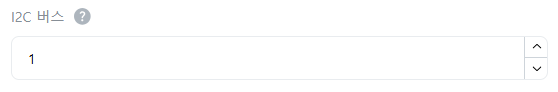
Example) For Raspberry Pi, the I2C bus number is 1.
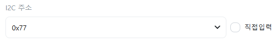


[I2C Address]

Select or manually enter the I2C address. For manual entry, use hexadecimal format like “0xFF”. This is displayed only when [Type] is “I2C”.
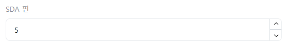

[SDA Pin]

Enter the GPIO number to use as the SDA pin. This is displayed only when [Type] is “I2C” and [Interface] is “Software”.


[SCL Pin]

Enter the GPIO number to use as the SCL pin. This is displayed only when [Type] is “I2C” and [Interface] is “Software”.


[SPI Bus]

Enter the hardware SPI bus number. This is displayed only when [Type] is “SPI” and [Interface] is “Hardware”.

The SPI bus number is shown on each hardware’s pin map.
Example) For Raspberry Pi, the SPI bus number is 0.


[CS (Chip Select)]

Enter the CS (Chip Select) number for hardware SPI. This is displayed only when [Type] is “SPI” and [Interface] is “Hardware”.


[CS Pin]

Enter the GPIO number to use as the CS pin. This is displayed only when [Type] is “SPI” and [Interface] is “Software”.


[SCLK Pin]

Enter the GPIO number to use as the SCLK pin. This is displayed only when [Type] is “SPI” and [Interface] is “Software”.


[MISO Pin]

Enter the GPIO number to use as the MISO pin. This is displayed only when [Type] is “SPI” and [Interface] is “Software”.
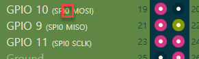

[MOSI Pin]

Enter the GPIO number to use as the MOSI pin. This is displayed only when [Type] is “SPI” and [Interface] is “Software”.


[Port]

Enter the serial port name. This is displayed only when [Type] is “UART”.


[1-Wire]

Under construction…


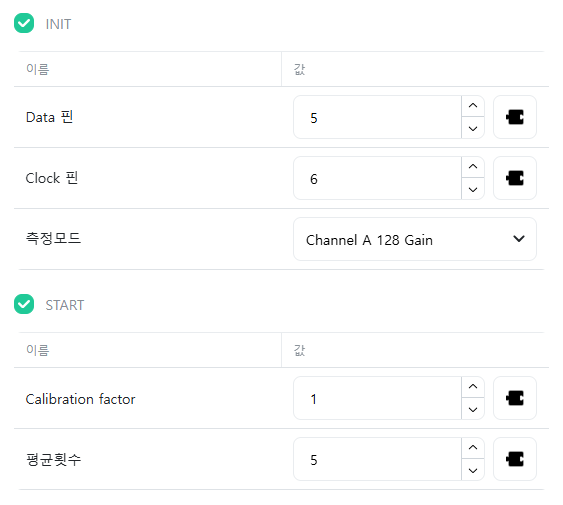
[Initialization Commands]

Initialization commands are the commands required to start the I/O device among the device’s commands. Enter the required values for each command. When the controller enters [RUN mode], the I/O device’s initialization commands are automatically executed to initialize the device.

If you uncheck the initialization command checkbox, that initialization command will not be executed, and you can also execute initialization commands in [Action] -> [I/O Device Control].


Edit

Click the icon of the item you want to edit.
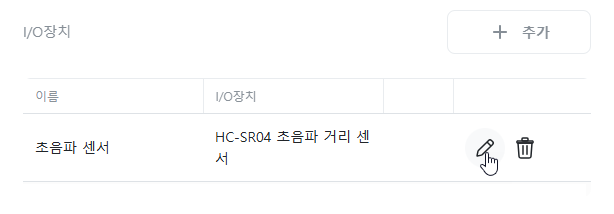


Delete

Click the icon of the item you want to delete.

찾으시는 내용이 없나요? 문의하기

문의하기

공유하기

I/O Device

Or copy link

Clipboard Icon
콘탠츠

ㅤ

Grablo Inc.
support@grablo.co

Site Links

  • Grablo Home
  • Grablo App

이 사이트의 모든 컨텐츠는 저작권법에 보호받는 저작물로서, 무단으로 복제, 배포하는 경우에는 저작권법에 의하여 처벌을 받을 수 있습니다. Copyright 2024 grablo.co. All Rights Reserved.