Pull-up/down Resistors
When connecting digital input devices such as push buttons to devices like Raspberry Pi and Arduino, you often see pull-up and pull-down resistors being connected.
In digital circuits, when an input pin is connected to VCC (power supply), it is recognized as HIGH, and when connected to GND, it is recognized as LOW.
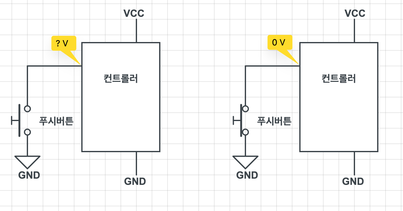
When a push button connected to a controller is pressed, the controller’s input pin voltage is connected to GND, making it 0V, or LOW. However, when the push button is not pressed, the input pin is not connected to either VCC (power supply) or GND, making it neither HIGH nor LOW. This is called a floating state, and it becomes an uncontrollable state as it can become HIGH or LOW due to noise, static electricity, etc.
Pull-up Resistor
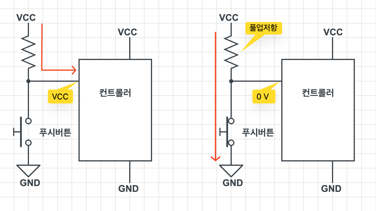
A resistor connected as shown below is called a pull-up resistor. When the push button is not pressed, current flows to the controller’s input pin, making it HIGH. When the push button is pressed, current flows to GND, making the controller input pin LOW.
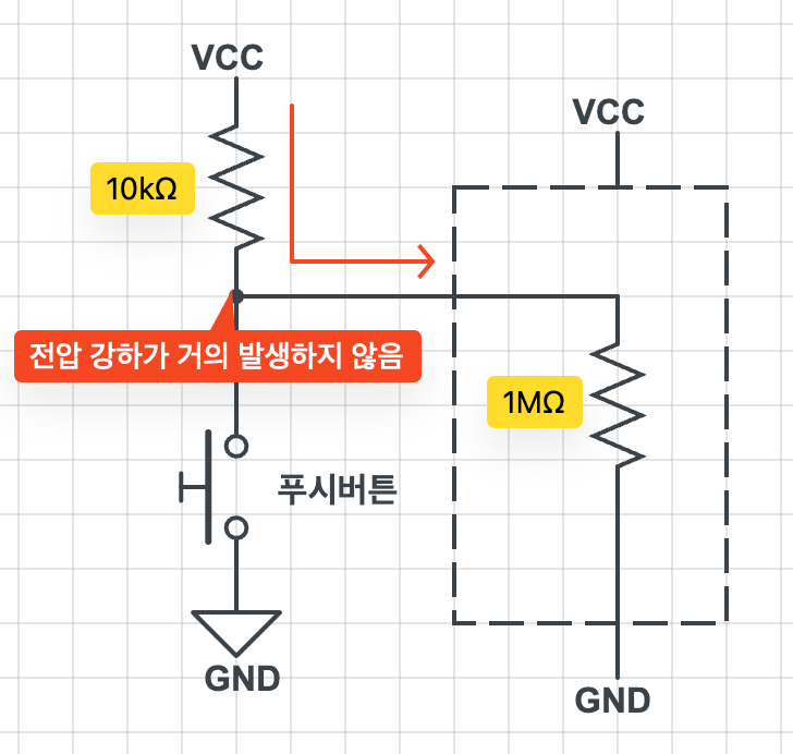
Since the impedance of the controller’s input pin (100k~1MOhm) is much larger than the pull-up resistor, virtually no voltage drop occurs at the bottom of the pull-up resistor when resistors are connected in series as shown in the figure below. (Series connection of resistors) Therefore, despite the presence of the pull-up resistor, a voltage close to the input voltage is applied to the input pin, making it recognized as HIGH.
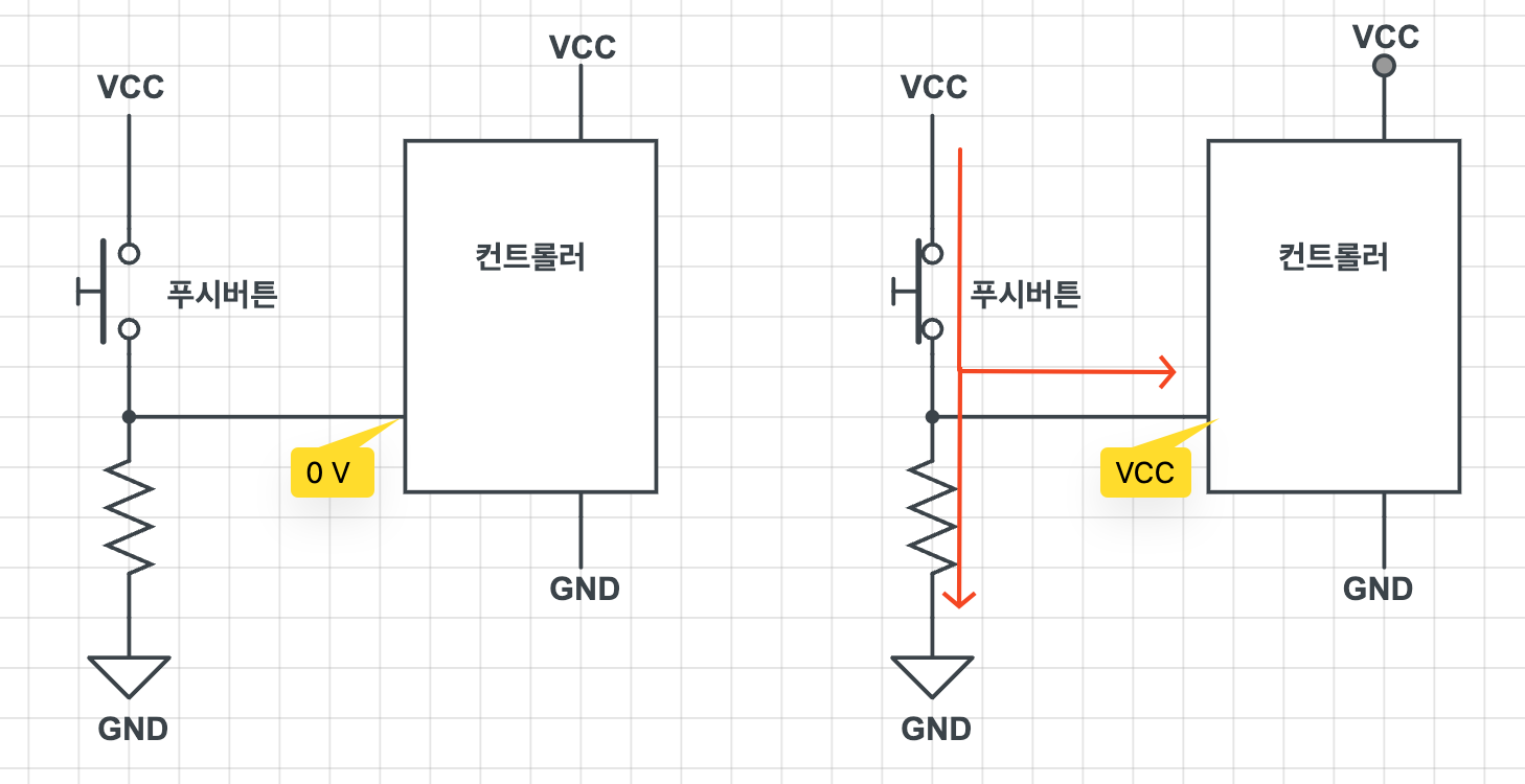
Pull-down Resistor
A resistor connected as shown below is called a pull-down resistor. When the push button is not pressed, the controller’s input pin is connected to GND, making it LOW. When the push button is pressed, current flows to the input pin, making it HIGH. In this case, the pull-down resistor serves to prevent excessive current flow to GND (short circuit).
Internal Pull-up/Pull-down Resistors
GPIO pins on devices like Raspberry Pi and BeagleBone have internal pull-up and pull-down resistors that can be activated through software. The resistance values of these resistors are suitable for most input devices such as push buttons, so there is no need to connect separate external resistors. Of course, external resistors can be added if needed.
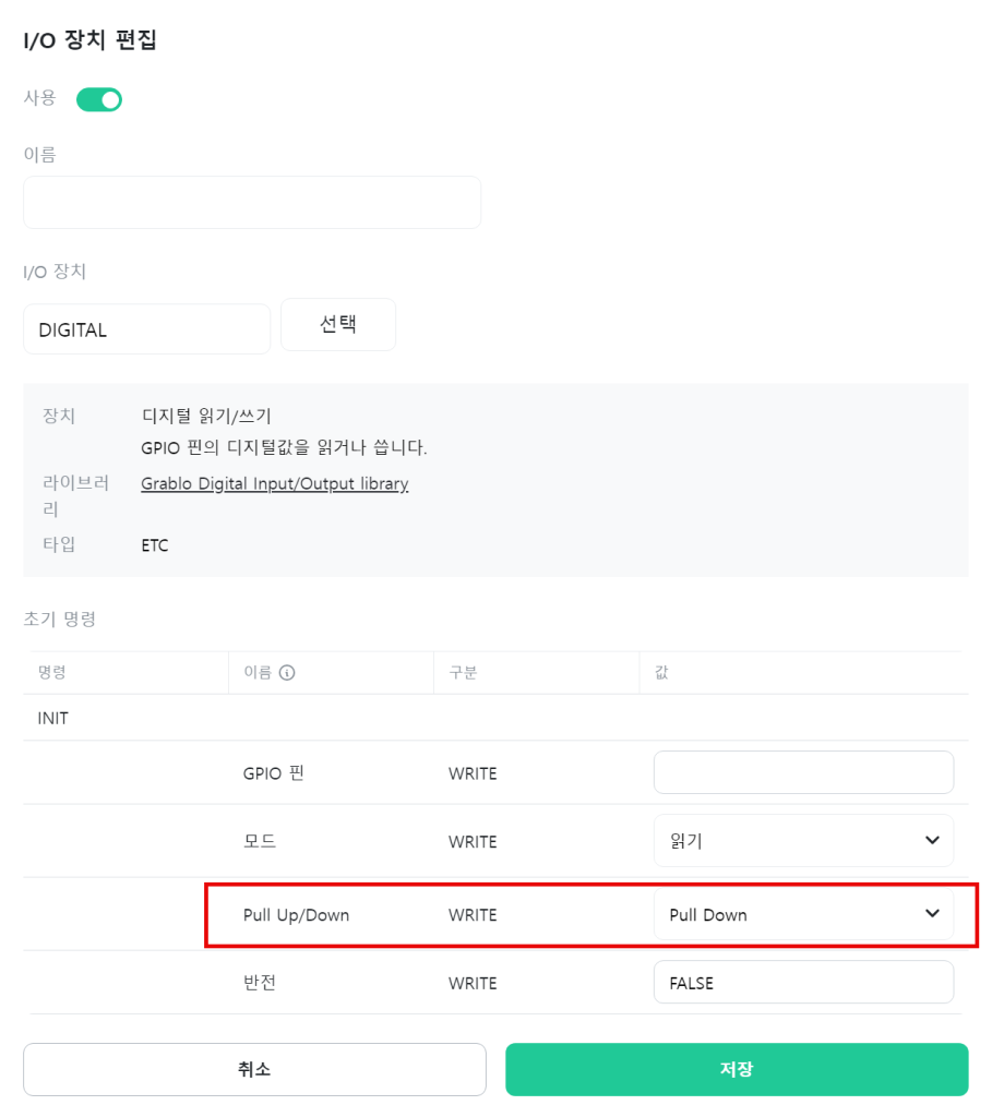
Pull-up/pull-down resistors can be configured in the INIT command for I/O devices – Digital Read/Write initialization.