Digital I/O
Overview
Read from or write to digital devices such as push buttons and LEDs.
Supported GPIO
- Raspberry Pi 0~4
- Raspberry Pi 5
- BeagleBone Black/Green
- Jetson Nano
- FT232H, FT2232H, FT4232H
- MCP2221
- NUMATO USB-GPIO (8~128CH)
Commands
[INIT]
Configures GPIO pin settings including pin number and mode.
| Item | Type | Description |
|---|---|---|
| GPIO Pin | WRITE | Enter the GPIO pin number to use. |
| Mode | WRITE | Select the mode (Input or Output). |
| Invert | WRITE | Set whether to invert the input or output signal. |
| Pull Up/Down * | WRITE | Configure internal GPIO pull-up/pull-down resistor (Off, Pull Down, Pull Up). |
* Only displayed when mode is “Input”.
* Works only with Linux kernel 5.10 or higher (Raspberry Pi OS, Ubuntu 22+, Debian 11+)
* For pull-up/pull-down explanation, refer to here.
* Works only with Linux kernel 5.10 or higher (Raspberry Pi OS, Ubuntu 22+, Debian 11+)
* For pull-up/pull-down explanation, refer to here.
[READ_PIN]
Reads the digital value from the GPIO pin.
| Item | Type | Description |
|---|---|---|
| Value | READ | Digital value read from the GPIO pin. |
[WRITE_PIN]
Writes a digital value to the GPIO pin.
| Item | Type | Description |
|---|---|---|
| Value | WRITE | Enter the digital value to write to the GPIO pin. |
Example
Objective
Turn on the LED only while the push button is pressed.
Parts
| Part | Quantity |
|---|---|
| Raspberry Pi 4 * | 1 |
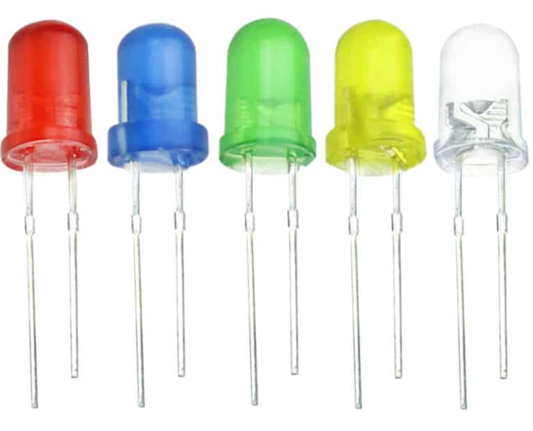
| Red LED | 1 |
| 220Ω Resistor ** | 1 |
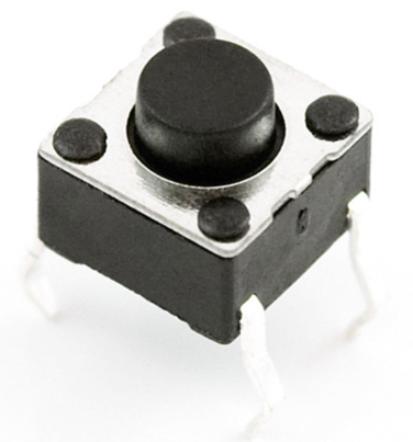
| Push Button | 1 |
* Other compatible hardware may be used. See Supported GPIO for details.
** For resistor value selection method, refer to here.
** For resistor value selection method, refer to here.
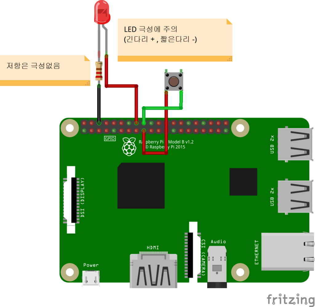
Wiring
Connect each component to the corresponding connection as listed in each row below.
| Component 1 | Component 2 | GPIO |
|---|---|---|
| Push Button Pin 1 | | 3.3V |
| Push Button Pin 2 | | 23 * |
| LED + Pin | | 24 * |
| LED – Pin | 220Ω Resistor | GND |
* All GPIO pins can be used.