
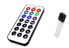
Infrared (IR) Receiver
Overview
A library that receives IR (infrared) signal input values. Can be used with infrared remote controls and similar devices.
Supported GPIO
- Raspberry Pi 0~4
- Raspberry Pi 5
- BeagleBone Black/Green
- Jetson Nano
Commands
[INIT]
Enters initial configuration settings.
| Item | Type | Description |
|---|---|---|
| GPIO Pin | WRITE | Enter the GPIO number to connect to the receiver’s OUT pin. |
[START]
Starts the device and waits for IR signal input.
[STOP]
Stops the module.
[READ_VALUE]
Reads the received value.
| Item | Type | Description |
|---|---|---|
| Received Value | READ | The received value. |
Example
Objective
Press buttons on an infrared remote control and display the received values on a dashboard widget.
Parts
| Part | Quantity |
|---|---|
| Raspberry Pi 4 * | 1 |
| IR Receiver | 1 |
| IR Remote Control | 1 |
| 1kΩ Resistor ** | 1 |
| 2kΩ Resistor ** | 1 |
* Other hardware can also be used. Refer to Supported GPIO.
** Resistors are only needed if the remote receiver is designed for 5V.
** Resistors are only needed if the remote receiver is designed for 5V.
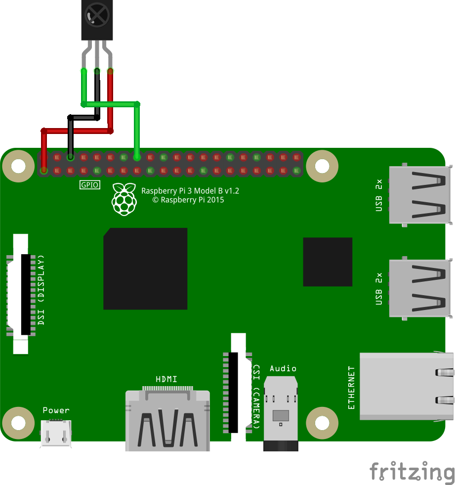
Wiring (3.3V)
Connect the following pins horizontally to each other.
If the remote receiver is designed for 3.3V, the OUT pin can be connected directly to GPIO.
| Receiver | GPIO |
|---|---|
| VCC | 3.3V |
| GND | GND |
| OUT | 23 * |
* Any GPIO pin can be used.
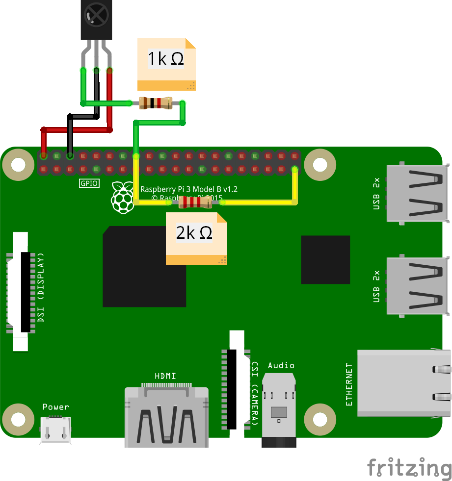
Wiring (5V)
Connect the following pins horizontally to each other.
If the receiver is designed for 5V, the OUT pin must be stepped down to 3.3V before connecting to GPIO. In this example, we use two resistors to create a voltage divider circuit.
| Remote Receiver | Resistor | GPIO | Resistor | GPIO |
|---|---|---|---|---|
| VCC | | 5V | | |
| GND | | GND | | |
| OUT | 1k Ω | 23 * | 2k Ω | GND |
* Any GPIO pin can be used.
Project Link
