
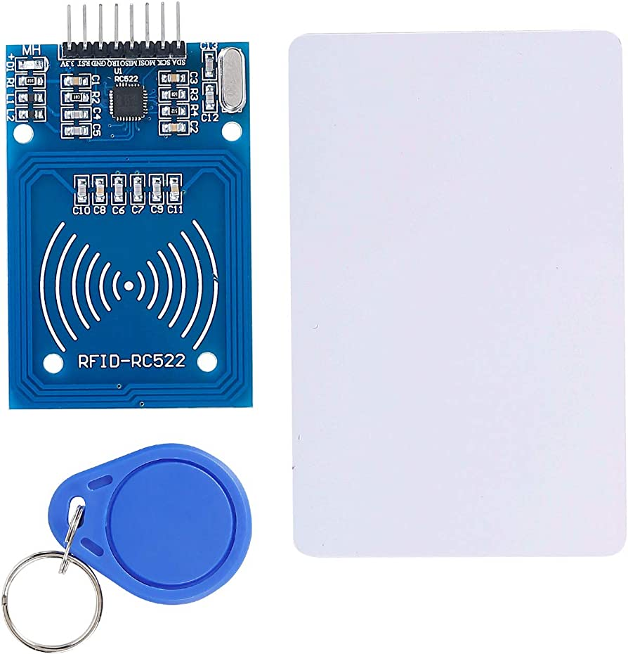
MFRC522 RFID Reader
Overview
RFID reader module based on MFRC522. Supports only MIFARE Classic type cards and uses SPI interface.
Specifications
- Power supply 3.3 V/5V
- Support ISO/IEC 14443 A/MIFARE
- Support mifare1 S50、mifare1 S70、mifare UltraLight、mifare Pro、mifare Desfire
- Operating distance in Read/Write mode up to 40 mm
- FIFO buffer handles 64 byte send and receive
- SPI interface
- Working current 13~26mA
- Idle current 10—13mA
- Working temperature -25 ~ 85℃
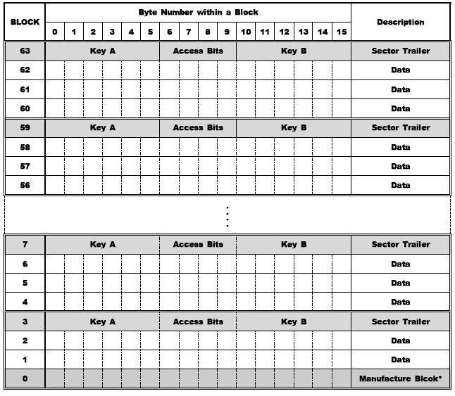
Structure of Mifare Classic Cards
The card’s internal storage is organized in Block units, where 1 Block is 16 bytes. Therefore, a 1kb card has a capacity of 64 blocks * 16 bytes = 1024 bytes (1kb).
Four blocks form one sector, and the last block of each sector is called the sector trailer, which is a block that sets the sector’s authentication keys and read/write permissions. Additionally, block 0 is the manufacture block that contains the card manufacturer code and serial number.
The table below shows the storage structure of a Mifare 1k card.
Therefore, when reading and writing user data, only blocks excluding the manufacture block and sector trailers should be used (blocks shown in white in the table below: 1,2, 4,5,6,…60,61,62).
Supported GPIO
- Raspberry Pi 0~4
- Raspberry Pi 5
- BeagleBone Black/Green
- Jetson Nano
- FT232H, FT2232H, FT4232H
Commands
[IS_NEW_CARD]
Returns true only once when a card is detected by the reader, and returns false in all other cases.
| Item | Type | Description |
|---|---|---|
| Card Detection | READ | Returns whether a card is detected. |
[READ_UID]
Reads the card type and UID. Available after card detection.
| Item | Type | Description |
|---|---|---|
| Type | READ | Returns the card type as text. |
| UID | READ | Returns the card’s Unique ID as a byte array. |
[READ_DATA]
Reads data stored on the card. Available after card detection.
| Item | Type | Description |
|---|---|---|
| Block Address | WRITE | Enter the block address of the card to read data from. |
| Data | READ | Data read from the block. Since it reads the entire block, the size is 16 bytes. |
[WRITE_DATA]
Writes up to 16 bytes of data to the card. Available after card detection.
| Item | Type | Description |
|---|---|---|
| Block Address | WRITE | The block address of the card to write data to. |
| Data | WRITE | Data to write to the block. Since it writes the entire block, if the data size is less than 16 bytes, the remaining space is filled with 0x00, and if it exceeds 16 bytes, only the first 16 bytes are written. |
[STOP]
Terminates operations related to the detected card. After detecting a card with the IS_NEW_CARD command and performing operations like READ/WRITE, this command must be executed to terminate the operations so that new cards can be detected.
Example
Objective
When a card is detected, display the card’s UID on a dashboard widget. Then write a random integer between 0-100 to block 1 of the card, read it back, and display it on a dashboard widget.
Parts
| Part | Quantity |
|---|---|
| Raspberry Pi 4 * | 1 |
| MFRC522 | 1 |
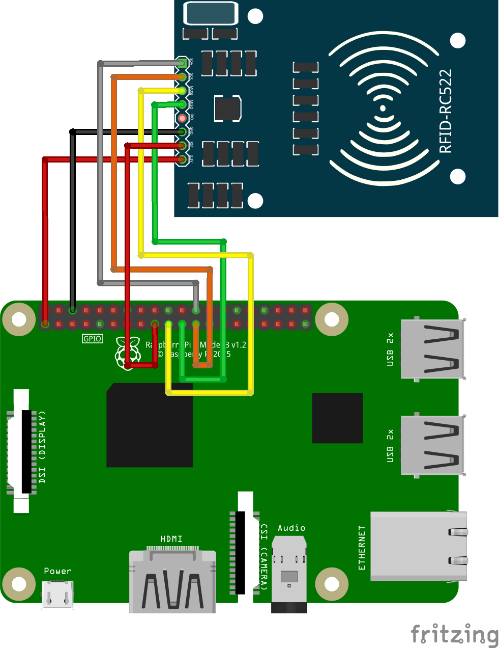
Wiring
Connect the following pins horizontally to each other.
| MFRC522 | GPIO |
|---|---|
| VIN(3.3V) | 3.3V |
| GND | GND |
| SCK | 11 (SPI0 SCLK) |
| MISO | 9 (SPI0 MISO) |
| MOSI | 10 (SPI0 MOSI) |
| SDA | 8 (SPI0 CE0) |
| RST | 3.3V |
Project Link
