
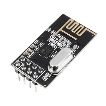
NRF24L01 2.4GHz RF Module
Overview
A low-power wireless communication module using 2.4GHz frequency. Primarily used for transmitting and receiving data in applications such as IoT and wireless sensor networks. Uses SPI interface.
Specifications
- IC:nRF24L01P
- Frequency:2.4~2.525GHz
- Power:20dBm
- Distance:2.5km
- Interface:SPI
Supported GPIO
- Raspberry Pi 0~4
- Raspberry Pi 5
- BeagleBone Black/Green
- Jetson Nano
- FT232H, FT2232H, FT4232H
Commands
[INIT]
Enters initial configuration settings.
| Item | Type | Description |
|---|---|---|
| ID | WRITE | Enter the module ID (address) in the range 0~255. The ID must be unique for each module and cannot be duplicated. |
| CE Pin | WRITE | Enter the GPIO number connected to the module’s CE pin. |
| Communication Speed | WRITE | Select the communication speed. Must match the communication speed of the counterpart. |
| Channel (0~125) | WRITE | Enter the communication channel in the range 0~125. Corresponds to the ISM band range of 2.400 ~ 2.525GHz, with each channel having a bandwidth of 1MHz. Must match the communication channel of the counterpart. |
[SEND]
Transmits data. Can send up to 32 bytes of data.
| Item | Type | Description |
|---|---|---|
| Recipient ID | WRITE | Enter the ID (address) of the recipient to send data to in the range 0~255. |
| Data | WRITE | Enter the data to send. Text format, up to 32 bytes can be sent. |
| Acknowledgment Request | WRITE | Select whether to request an acknowledgment signal (ACK) from the recipient confirming that they received the data after sending. If an acknowledgment request is sent but the recipient does not send an acknowledgment response, the data will be retransmitted up to 16 times. Recommended for environments where communication reliability is more important. |
[RECV]
Receives data.
| Item | Type | Description |
|---|---|---|
| Data | READ | Select a text type variable to store the received data. |
Example
Objective
Use two NRF24L01 modules to exchange data.
Parts
| Part | Quantity |
|---|---|
| Raspberry Pi 4 * | 2 |
| NRF24L01 | 2 |
| 10μF Electrolytic Capacitor (Optional) ** | 2 |
| 0.1μF Ceramic Capacitor (Optional) *** | 2 |
* Other hardware can also be used. Refer to Supported GPIO.
** The NRF24L01 module requires momentarily high current when transmitting data. If the power supply cannot respond fast enough, voltage drops may occur. Connecting a 10μF capacitor between 3.3V and GND can prevent this problem. Not necessary for testing purposes.
*** The NRF24L01 module uses high-frequency signals, which can cause noise on the power lines. The 0.1μF capacitor filters high-frequency noise, improving module stability. Connect in parallel with the 10μF capacitor. Not necessary for testing purposes.
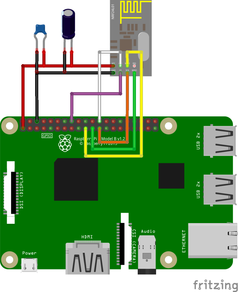
Wiring
Connect the following pins horizontally to each other. (2 sets)
| NRF24L01 * | 10μF Electrolytic Capacitor | 0.1μF Ceramic Capacitor | GPIO |
|---|---|---|---|
| + Pin | 3.3V | ||
| – Pin | GND | ||
| Pin 1 | 3.3V | ||
| Pin 2 | GND | ||
| VCC | 3.3V | ||
| GND | GND | ||
| SCLK | 11 (SPI0 SCLK) | ||
| MISO | 9 (SPI0 MISO) | ||
| MOSI | 10 (SPI0 MOSI) | ||
| CSN | 8 (SPI0 CE0) | ||
| CE | 23 ** |
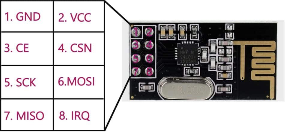
* NRF24L01 modules do not have pin names marked. Refer to the diagram below.
** Any GPIO pin can be used.
** Any GPIO pin can be used.
Project Link
