PCA9685 16-Channel 12-Bit PWM Servo Driver
Overview
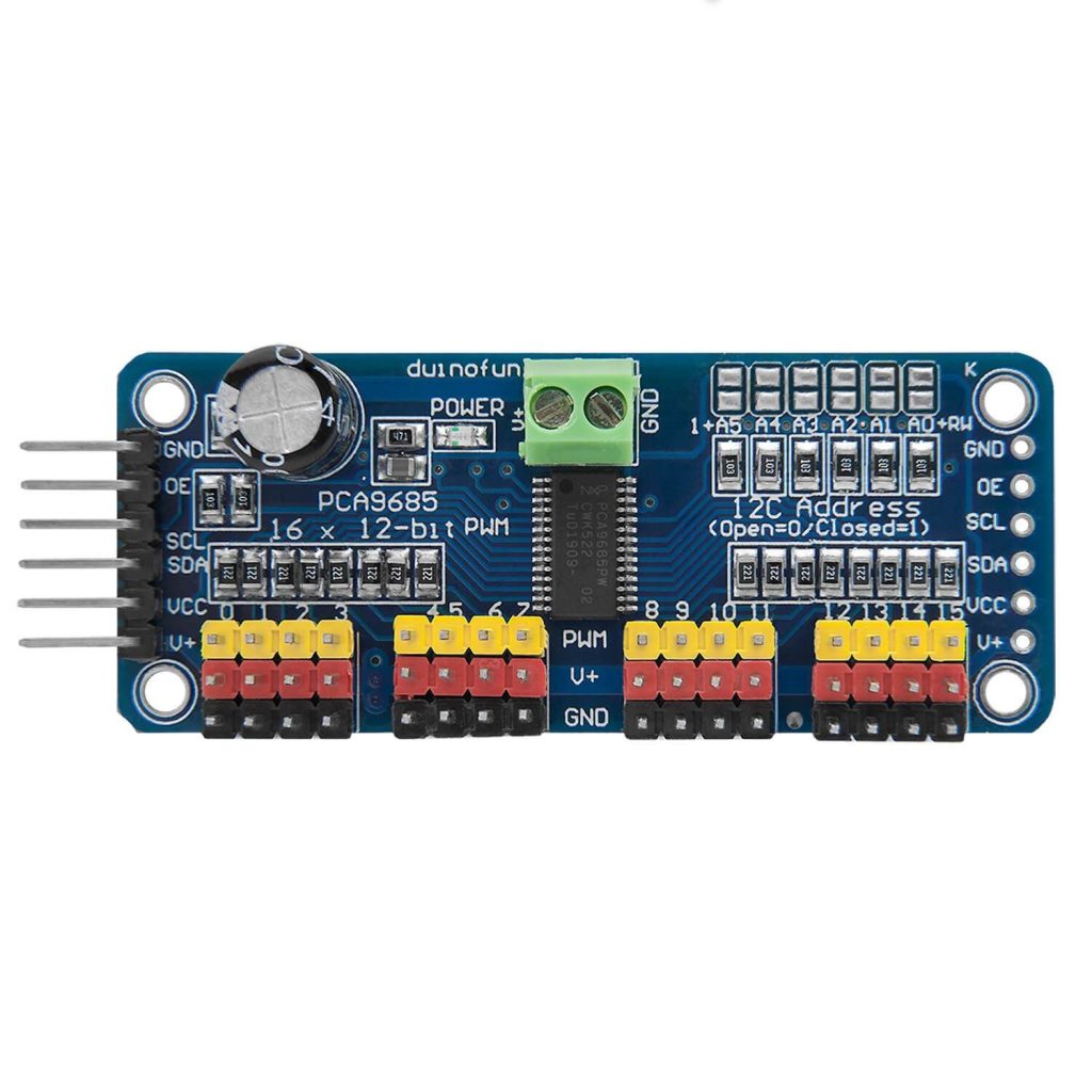
A 16-channel, 12-bit PWM (Pulse Width Modulation) driver capable of controlling multiple servo motors and LEDs. It can be used in various applications such as robots, drones, RC vehicles, and lighting control. Uses I2C interface.
Supported GPIO
- Raspberry Pi 0~4
- Raspberry Pi 5
- BeagleBone Black/Green
- Jetson Nano
- FT232H, FT2232H, FT4232H
- MCP2221
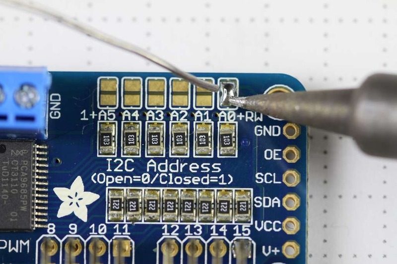
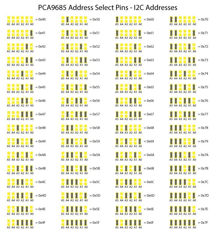
I2C Address
Different I2C addresses can be set depending on whether the A0~A5 jumpers on the board are connected.
Commands
[INIT]
Enters initial configuration settings.
| Item | Type | Description |
|---|---|---|
| Frequency (Hz) * | WRITE | Sets the output frequency. (24~1526Hz) |
Different frequencies cannot be set for each channel; the same frequency setting applies to all channels.
When controlling servo motors, a 50Hz frequency must be used.
When controlling servo motors, a 50Hz frequency must be used.
[SET_PWM]
Outputs PWM signal. You can set the offset where the HIGH signal starts and the duty cycle where the HIGH signal is maintained as percentages.
| Item | Type | Description |
|---|---|---|
| Channel | WRITE | Enter the channel (pin) number to output the PWM signal. (0~15) |
| Offset (%) | WRITE | Enter the offset where HIGH starts in the PWM cycle. (0~100%) |
| Duty Cycle (%) | WRITE | Enter the duty cycle where HIGH is maintained in the PWM cycle. (0~100%) |
[SET_SERVO]
Sets the position of the servo motor.
| Item | Type | Description |
|---|---|---|
| Channel | WRITE | Enter the channel (pin) number to output the PWM signal. (0~15) |
| Pulse Width (ms) * | WRITE | Enter the input pulse width in ms. |
* The pulse width for servo motor angle or speed may vary by product, but is generally as follows:
– 1ms (minimum position) ~ 2ms (maximum position) or 0.544ms (minimum position) ~ 2.4ms (maximum position)
– If the motor does not rotate to the input angle, the input pulse width should be adjusted appropriately by referring to the product specifications.
– 1ms (minimum position) ~ 2ms (maximum position) or 0.544ms (minimum position) ~ 2.4ms (maximum position)
– If the motor does not rotate to the input angle, the input pulse width should be adjusted appropriately by referring to the product specifications.
Example
Objective
Control the servo motor angle by changing the pulse width in the range of 0.5~2.4ms using a dashboard slider widget.
Parts
| Part | Quantity |
|---|---|
| Raspberry Pi 4 * | 1 |
| PCA9685 | 1 |
| Servo Motor | 1 |
* Other hardware can also be used. Refer to Supported GPIO.
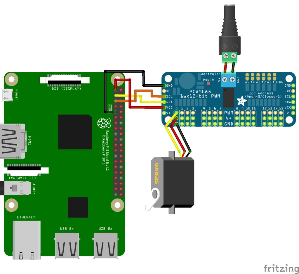
Wiring
Connect the following pins horizontally to each other.
| DC Power * | PCA9685 | Servo Motor | GPIO |
|---|---|---|---|
| + | V+ | ||
| – | GND | ||
| VCC | 3.3V | ||
| GND | GND | ||
| SCL | 3 (I2C1 SCL) | ||
| SDA | 2 (I2C1 SDA) | ||
| PWM 0 | Yellow or Orange | ||
| V+ | Red | ||
| GND | Black or Brown |
* Connect DC power that matches the voltage and current consumption of the servo motor being used.