PWM Signal Monitoring
Overview
Monitors incoming PWM signals to measure frequency, pulse width, and duty cycle.

Supported GPIO
- Raspberry Pi 0~4
- Raspberry Pi 5
- BeagleBone Black/Green
- Jetson Nano
On hardware other than Raspberry Pi 0~4, measurement accuracy may decrease at frequencies above 1000Hz.
Commands
[INIT]
Configures initial settings for PWM monitoring.
| Item | Type | Description |
|---|---|---|
| GPIO Pin | WRITE | Enter the GPIO pin number to monitor PWM signals. |
| Timeout Duration | WRITE | If no GPIO pin changes occur during the timeout period, frequency, pulse width, and duty cycle are all reset to 0. |
| Weight (%) | WRITE | Sets how much influence previous measurements have on new measurements. Value between 0~99% that helps smooth transitions when sudden PWM changes occur. |
[START]
Starts PWM monitoring.
[STOP]
Stops PWM monitoring.
[READ_DATA]
Reads measured frequency, pulse width, and duty cycle.
| Item | Type | Description |
|---|---|---|
| Frequency (Hz) | READ | Measured frequency. |
| Pulse Width (us) | READ | Measured pulse width. |
| Duty Cycle (%) | READ | Measured duty cycle. |
Example
Objective
Output a 1000Hz PWM signal and change the duty cycle from 0-100% using a dashboard slider widget. Display the monitored PWM signal’s frequency (Hz), pulse width (us), and duty cycle (%) on dashboard widgets.
Parts
| Part | Quantity |
|---|---|
| Raspberry Pi 4 * | 1 |
* Other compatible hardware may be used. See Supported GPIO for details.
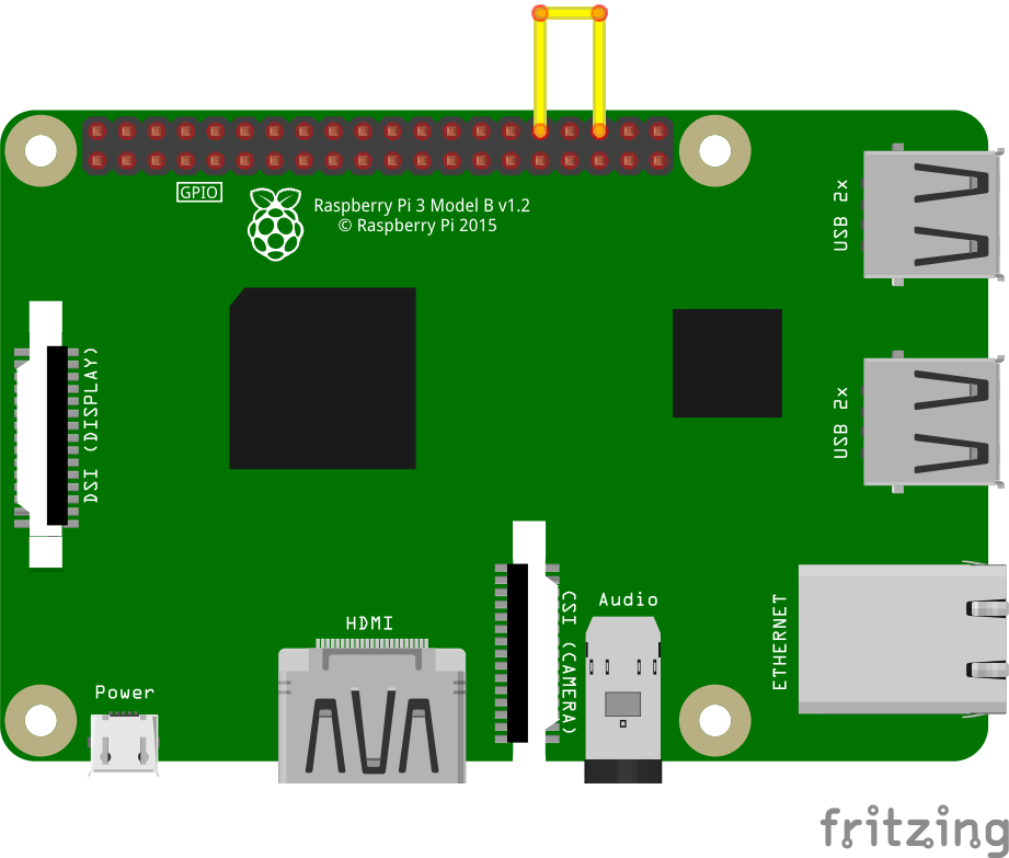
Wiring
Connect the pins as listed in each row below.
| GPIO | GPIO |
| 12 (PWM0) | 16 |