PWM Signal Output
Overview
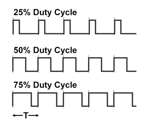
Generates PWM (Pulse Width Modulation) output with configurable frequency (Hz) and duty cycle (%). Can be used for various purposes including LED brightness control, servo motors, DC motor control, etc. Available only on Raspberry Pi 0~4.
All GPIO pins can be used, but output frequency is limited to one of the following frequencies:
10, 20, 40, 50, 80, 100, 160, 200, 250, 320, 400, 500, 800, 1000, 1600, 2000, 4000, 8000 Hz (based on 5us GPIO sample time)
If you need freely configurable output frequency, use Hardware PWM Signal Output.
10, 20, 40, 50, 80, 100, 160, 200, 250, 320, 400, 500, 800, 1000, 1600, 2000, 4000, 8000 Hz (based on 5us GPIO sample time)
If you need freely configurable output frequency, use Hardware PWM Signal Output.
Supported GPIO
- Raspberry Pi 0~4
Commands
[INIT]
Configures PWM frequency and resolution (Full Step Range).
| Item | Type | Description |
|---|---|---|
| GPIO Pin | WRITE | Sets the GPIO pin to use for PWM output. |
| Frequency (Hz) | WRITE | Sets the output frequency (0~8,000Hz). |
| Full Step Range * | WRITE | Sets the resolution of the output signal (25~40,000). |
* Sets how finely the duty cycle can be controlled.
Example: 255 -> Allows duty cycle adjustment in 255 steps from 0~100%.
Example: 255 -> Allows duty cycle adjustment in 255 steps from 0~100%.
[SET_DUTY_CYCLE]
Outputs PWM signal with the specified duty cycle.
| Item | Type | Description |
|---|---|---|
| Duty Cycle (%) | WRITE | Outputs PWM signal with the specified duty cycle (0~100%). |
[READ_PWM]
Reads actual information of the output PWM signal.
| Item | Type | Description |
|---|---|---|
| Frequency(Hz) * | READ | Actual output frequency. |
| Full Step Range | READ | Actual output resolution (Full Step Range). |
| Step ** | READ | Actual output step value. |
* If the user-specified frequency doesn’t match one of the supported frequencies, the closest available frequency will be output.
** Example: Full step range 250, 50% duty cycle → 125
** Example: Full step range 250, 50% duty cycle → 125
Example
Objective
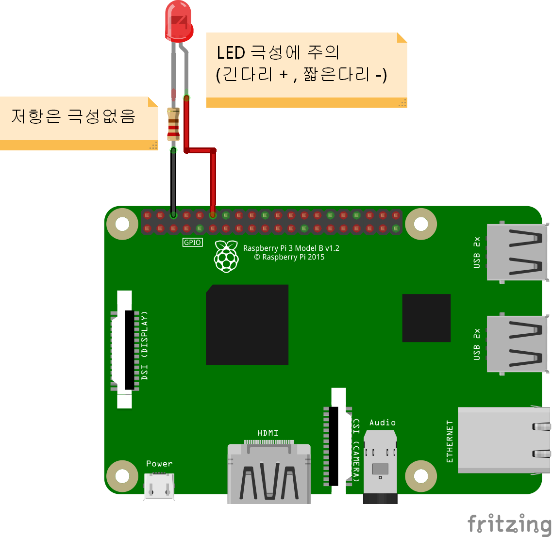
Control the brightness of a red LED by adjusting the PWM signal duty cycle from 0-100% using a dashboard slider widget.
Parts
| Part | Quantity |
|---|---|
| Raspberry Pi 4 | 1 |
| Red LED | 1 |
| 220Ω Resistor * | 1 |
* For resistor value selection method, refer to here.
Wiring
Connect each component to the corresponding connection as listed in each row below.
| Component 1 | Component 2 | GPIO |
|---|---|---|
| LED + Pin | | 18 |
| LED – Pin | 220Ω Resistor | GND |